


MDS-D-SVJ3/SPJ3 Series Specifications Manual
2-4 Drive unit
2 - 25
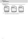
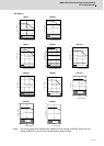
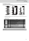
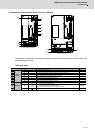
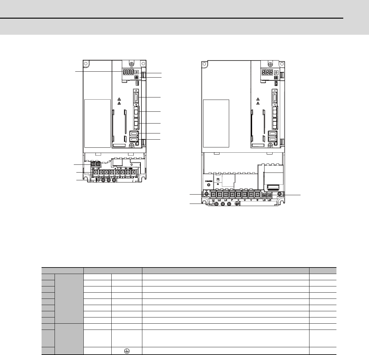
(3) Explanation of each spindle drive unit (5.5 to 11kW) part
The connector and terminal block layout may differ according to the unit being used. Refer to each unit
outline drawing for details.
<Each part name>
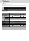
Name Description Screw size
(1)
Control
circuit
LED --- Unit status indication LED ---
(2) SW1 --- Axis No. setting switch ---
(3) SW2 --- For machine tool builder adjustment: Always OFF (facing bottom) ---
(4) CN9 --- DI/O or maintenance connector ---
(5) CN1A --- NC or master axis optical communication connector ---
(6) CN1B --- Slave axis optical communication connector ---
(7) CN2 --- Motor side detector connection connector ---
(8) CN3 --- Machine side detector connection connector ---
(9)
Main circuit
TE2 L11,L21 Control power input terminal (single-phase AC input) M3.5×6
(10) TE1
L1,L2,L3
P,C
U, V, W
L1,L2,L3: 3-phase AC power input
P,C: Regenerative resistor connection terminal
U,V,W: Motor power output terminal (3-phase AC output)
M4×10
(11) PE Grounding terminal M4×10
(5)
(6)
(8)
(7)
(1)
(2)
(10)
(9)
(11)
(3)
(4)
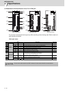
(10)
(11)
(9)
MDS-D-SPJ3-55NA/75NA
MDS-D-SPJ3-110NA