


4 - 3
MDS-D-SVJ3/SPJ3 Series Specifications Manual
4-1 Servomotor
4-1-3 Shaft characteristics
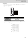
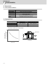
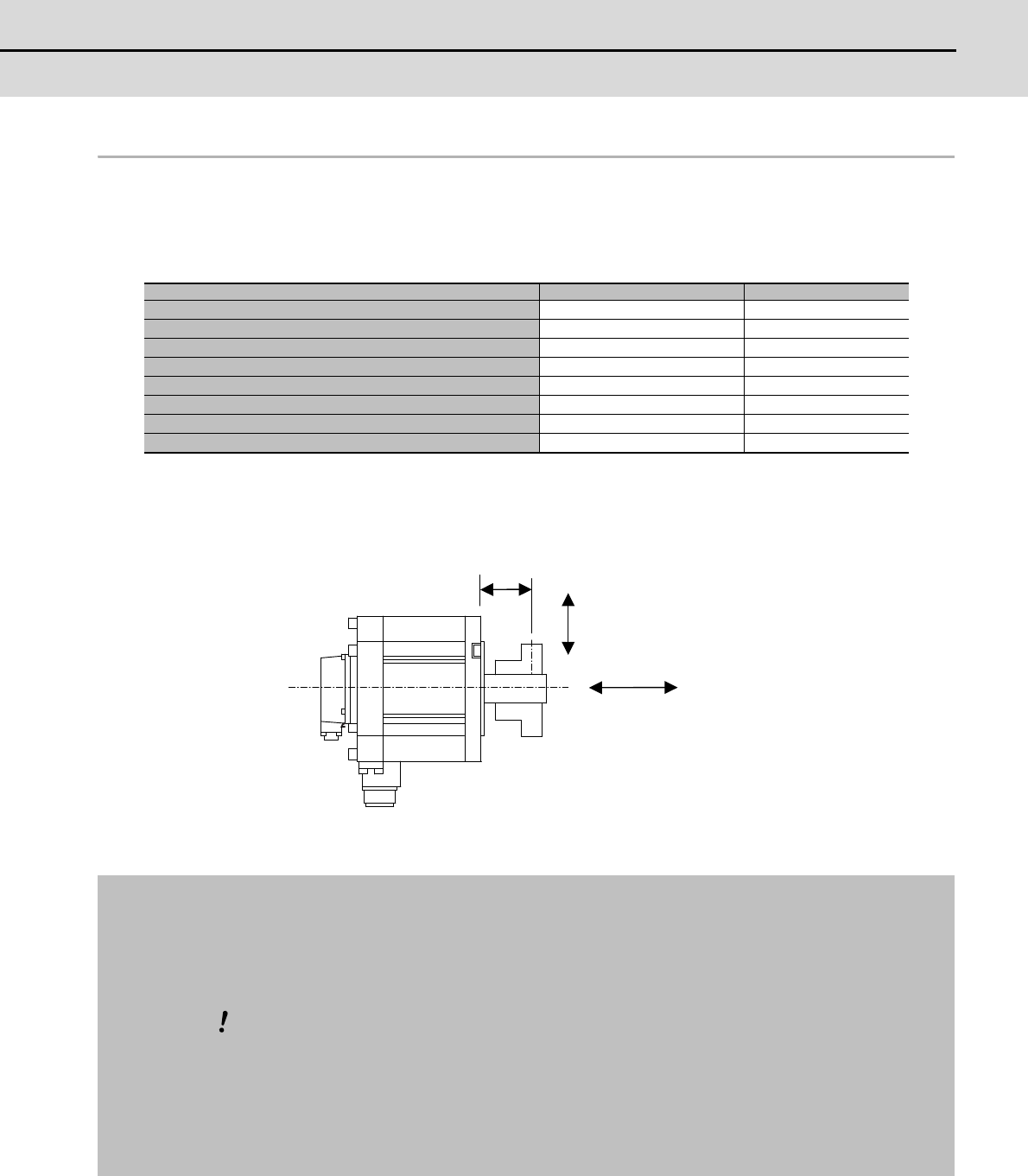
There is a limit to the load that can be applied on the motor shaft. Make sure that the load applied on the
radial direction and thrust direction, when mounted on the machine, is below the tolerable values given
below. These loads may affect the motor output torque, so consider them when designing the machine.
(Note 1) The tolerable radial load and thrust load in the above table are values applied when each motor is
used independently.
(Note 2) The symbol L in the table refers to the value of L below.
L: Length from flange installation surface to center of load mass [mm]
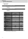
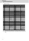
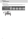
Servomotor Tolerable radial load Tolerable thrust load
HF75T, 105T (Taper shaft) 245N (L=33) 147N
HF75S, 105S (Straight shaft) 245N (L=33) 147N
HF54T, 104T, 154T, 224T,123T, 223T, 142T (Taper shaft) 392N (L=58) 490N
HF54S, 104S, 154S, 224S,123S, 223S, 142S (Straight shaft) 980N (L=55) 490N
HF204S, 354S, 303S, 302S (Straight shaft) 2058N (L=79) 980N
HF-KP13 (Straight shaft) 88N (L=25) 59N
HF-KP23, 43 (Straight shaft) 245N (L=30) 98N
HF-KP73 (Straight shaft) 392N (L=40) 147N
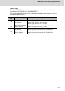
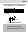
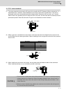
1. Use a flexible coupling when connecting with a ball screw, etc., and keep the shaft core deviation
to below the tolerable radial load of the shaft.
2. When directly installing the gear on the motor shaft, the radial load increases as the diameter of the
gear decreases. This should be carefully considered when designing the machine.
3. When directly installing the pulley on the motor shaft, carefully consider so that the radial load
(double the tension) generated from the timing belt tension is less than the values shown in the
table above.
4. In machines where thrust loads such as a worm gear are applied, carefully consider providing
separate bearings, etc., on the machine side so that loads exceeding the tolerable thrust loads are
not applied to the motor.
Radial load
Thrust load
L
CAUTION