


2-2
Cell Site Configurations
411-2021-111 Standard 01.01 June 1996
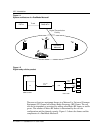
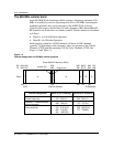
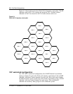
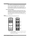
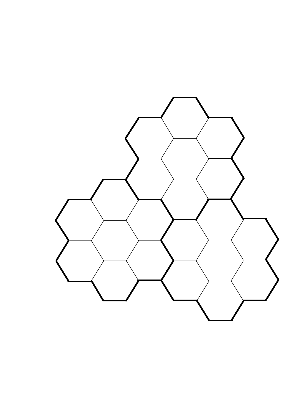
Figure 2-1 shows the layout of an Omni (N=7) frequency reuse plan;. The RF
channels used in Cell 1 of a cluster are reused in Cell 1 of other clusters,
channels in Cell 2 are reused in Cell 2 of other clusters and so on.
Figure 2-1
Omni (N=7) frequency reuse plan
120
°
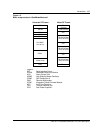
sectorized configuration
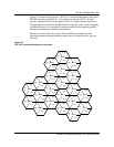
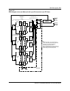
In a 120
°
(N=7) sectorized configuration, the 416 RF channels are divided
among a cluster of seven cells. Each cell contains a maximum of 59 or 60 RF
channels, with three Control channels for each cell. Since each cell is further
divided into three sectors, each sector will contain a maximum of 19 or 20 RF
channels, with one Control channel for each sector. The available RF
channels are reused by other groups of cells within the system.
CELL 7
CELL 6
CELL 1
CELL 4
CELL 5
CELL 2
CELL 7
CELL 6 CELL 3
CELL 6
CELL 5
CELL 1
CELL 7
CELL 4
CELL 3
CELL 2
CELL 1
CELL 5
CELL 2
CELL 4
CELL 3