


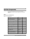
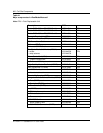

Power and Grounding Requirements
5-5
DMS-MTX DualMode Metrocell Cell Site Description
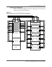
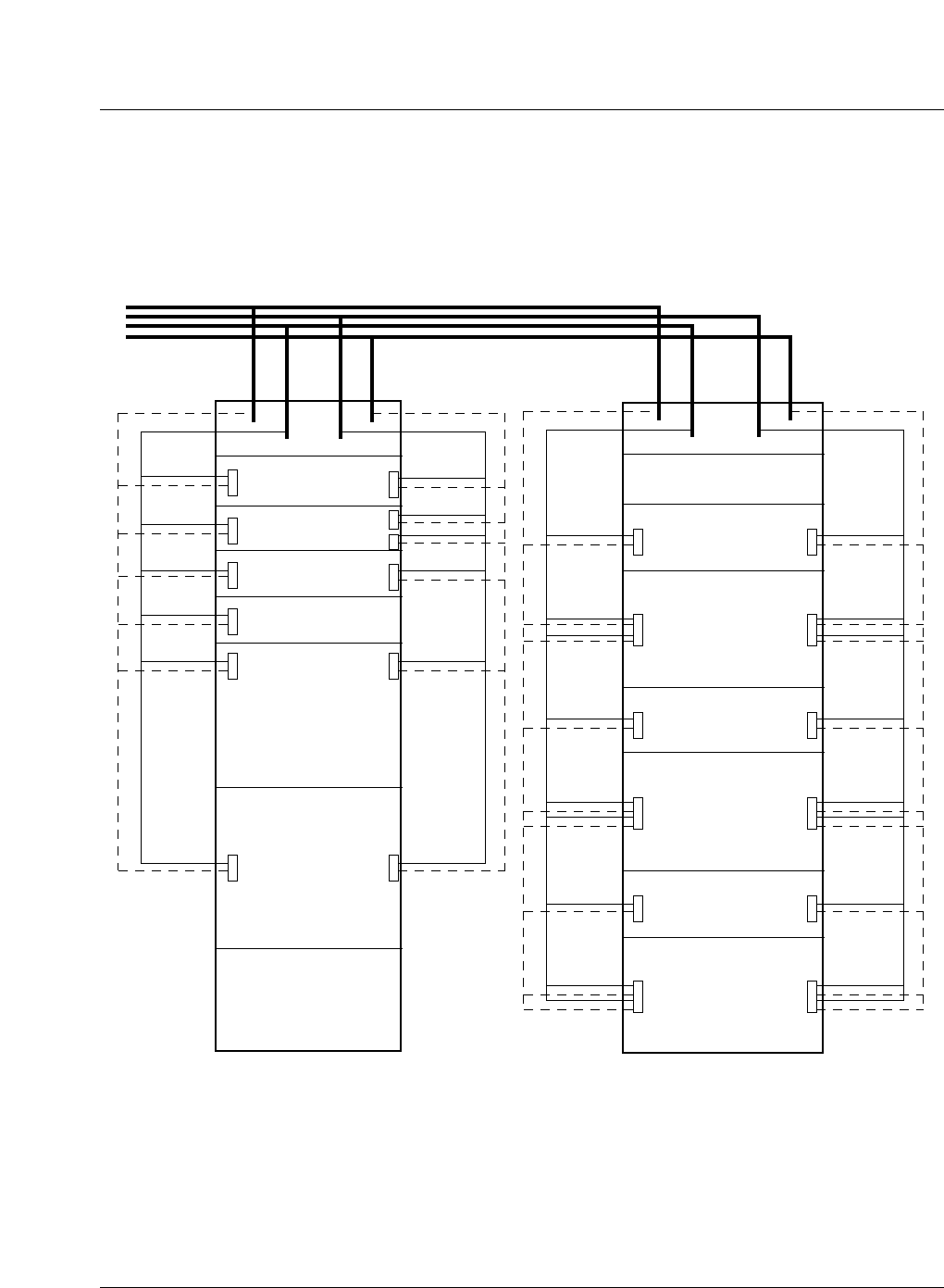
Frame power distribution
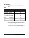
Figure 5-1 shows the distribution network for supplying power to the cell site
components in the CE and RF Frames.
Figure 5-1
Power distribution for the CE and RF Frames in a Metrocell
TRU/PA Shelf 1
ATC Shelf 1
Duplexer Shelf
RIP/Breaker
TRU/PA Shelf 2
ATC Shelf 2
TRU/PA Shelf 3
ATC Shelf 3
A-Pwr
B-Pwr
A-Gnd
B-Gnd
TRU 1,2
DPA 1
TRU 5,6
DPA 3
TRU 3,4
DPA 2
TRU 7,8
DPA 4
TRU 9,10
DPA 5
TRU 13,14
DPA 7
TRU 11,12
DPA 6
TRU 15,16
DPA 8
TRU 17,18
DPA 9
TRU 21,22
DPA 11
TRU 19,20
DPA 10
TRU 23,24
DPA 12
Breaker1
Breaker2
Breaker4
Breaker5
Breaker7
Breaker8
Breaker6
Breaker9
Breaker3
Breaker20
Breaker19
Breaker17
Breaker16
Breaker14
Breaker13
Breaker15
Breaker12
Breaker18
Blank
ICRM Shelf
DRUM Shelf
RIP/Breaker
RMC Shelf
(one to six)
CSM2 Shelf
HSMO Shelf
ACU Shelf
A-Pwr
B-Pwr
A-Gnd
B-Gnd
Breaker5
Breaker3
Breaker4
Breaker2
Breaker8
Breaker13
Breaker10
Breaker16
Breaker1
Breaker9
Breaker12
Breaker11