


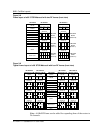
3-26 Cell Site Layouts
411-2021-111 Standard 01.01 June 1996
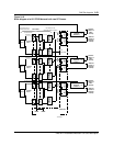
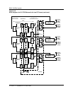
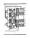
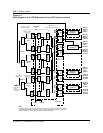
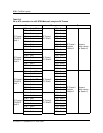
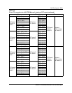
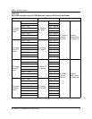
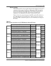
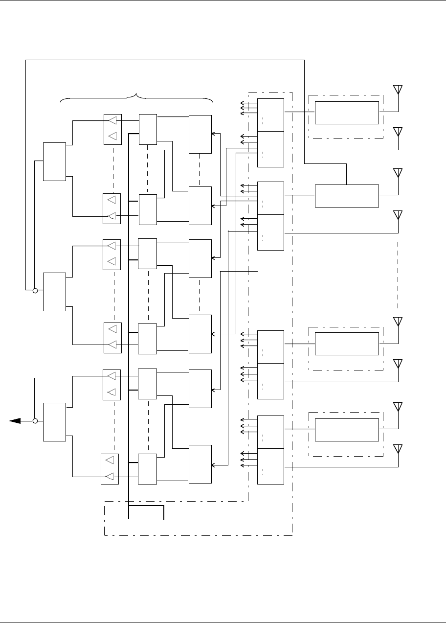
Figure 3-11
Block diagram of a 60° STSR Metrocell with four RF Frames (continued)
Control Channel
for Sector Z
Note:
TRU 1
6 5 4 3 2 1
TRU SHELF
SPLITTER 1
TRU SHELF
SPLITTER 6
ICRM HSMO
RF Frame 2
Note
TRU 8
6 5 4 3 2 1
TRU 9
6 5 4 3 2 1
TRU 16
6 5 4 3 2 1
Duplexer
Position 2
RX ANT
TX
B1
B2
B8
A1
A2
A8
RMC 1A
RMC 1B
Antenna
(Sector X
Main
receive)
Antenna
(Sector X
Diversity
receive)
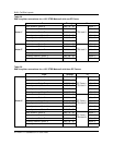
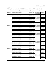
See Table 3-15 for
RMC/TRU Shelf connection
TRU SHELF
SPLITTER 1
TRU SHELF
SPLITTER 6
TRU/DPA
Shelf 1
TRU/DPA
Shelf 2
ATC 1
ATC 2
See Tables 3-13 for
PA/ATC connection
Control Channel
for Sector Y
CE Frame
TRU 17
6 5 4 3 2 1
TRU 24
6 5 4 3 2 1
TRU SHELF
SPLITTER 1
TRU SHELF
SPLITTER 6
TRU/DPA
Shelf 3
ATC 3
A3
B3
B1
B2
B8
A1
A2
A8
RMC 2A
RMC 2B
Antenna
(Sector Y
Main
receive)
Antenna
(Sector Y
Diversity
receive)
A3
B3
B1
B2
B8
A1
A2
A8
RMC 6A
RMC 6B
Antenna
(Sector W
Main
receive)
Antenna
(Sector W
Diversity
receive)
A3
B3
DPA 12
DPA 1
DPA 4
DPA 5
DPA 8
DPA 9
Duplexer
Position 2
RX ANT
TX
RF Frame 1
Duplexer
Position 3
RX ANT
TX
RF Frame 3
B1
B2
B8
A1
A2
A8
RMC 5A
RMC 5B
Antenna
(Sector V
Main
receive)
Antenna
(Sector V
Diversity
receive)
A3
B3
Duplexer
Position 2
RX ANT
TX
RF Frame 4
Sector Y
Sector Z
From
RMC 3A-A3
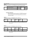
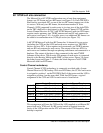
For diagram clarity, only RF Frames 1 and 2 are shown. RF Frames 3 and 4 are connected
and operated identically to that of RF Frames 1 and 2 respectively for Sectors U, V and W.
Refer to Tables 3-13 and 3-15 for the complete cabling information.
To Sector Z
Main Antenna
through
Duplexer 3 on
RF Frame 2
From ATC 3 on
RF Frame 1