


Cell Site Layouts 3-27
DMS-MTX DualMode Metrocell Cell Site Description
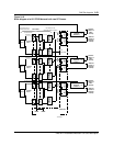
Transmit cabling
In the transmit path, the output of each Transmit Receive Unit (TRU) is
connected to the input of each corresponding power amplifier (PA) on the
Dual Power Amplifier (DPA) module.
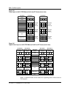
For a 60° STSR cell site with two RF Frames, each TRU/DPA Shelf and its
associated ATC and duplexer serve for one of the six sectors as listed below:
• Sector X RF Frame 1—TRU/DPA Shelf 1, ATC 1 and Duplexer 1
• Sector Y RF Frame 1—TRU/DPA Shelf 2, ATC 2 and Duplexer 2
• Sector Z RF Frame 1—TRU/DPA Shelf 3, ATC 3 and Duplexer 3
• Sector U RF Frame 2—TRU/DPA Shelf 1, ATC 1 and Duplexer 1
• Sector V RF Frame 2—TRU/DPA Shelf 2, ATC 2 and Duplexer 2
• Sector W RF Frame 2—TRU/DPA Shelf 3, ATC 3 and Duplexer 3
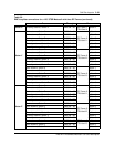
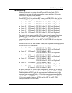
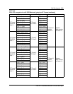
The output of each power amplifier (PA) is input to an 8-channel AutoTune
Combiner (ATC). The output of each 8-channel ATC is connected to the
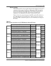
Transmit (TX) port of each corresponding duplexer. Table 3-12 lists the
connection between the PAs and the ATC for a 60° STSR cell site using two
RF Frame for six sectors.
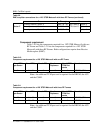
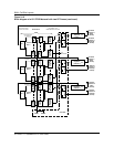
For a 60° STSR cell site with four RF Frames, the assignment of the equipment
for each sector is as listed below:
• Sector X RF Frame 1 —TRU/DPA Shelf 1, ATC 1
TRU/DPA Shelf 2, ATC 2 and Duplexer 2
• Sector Y RF Frame 2 —TRU/DPA Shelf 1, ATC 1
TRU/DPA Shelf 2, ATC 2 and Duplexer 2
• Sector Z RF Frame 1 —TRU/DPA Shelf 3, ATC 3
RF Frame 2 —TRU/DPA Shelf 3, ATC 3 and Duplexer 3
• Sector U RF Frame 3 —TRU/DPA Shelf 1, ATC 1
TRU/DPA Shelf 2, ATC 2 and Duplexer 2
• Sector V RF Frame 4 —TRU/DPA Shelf 1, ATC 1
TRU/DPA Shelf 2, ATC 2 and Duplexer 2
• Sector W RF Frame 3 —TRU/DPA Shelf 3, ATC 3 and Duplexer 3
RF Frame 4 —TRU/DPA Shelf 3, ATC 3
By adding one more RF Frame to this configuration, three of the six sectors
can be expanded to provide up to 24 channels (including the CCH and LCR).
With this additional RF Frame, the equipment and cabling may need to be
reassigned and rearranged. Table 3-12 lists the connection between the PAs
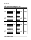
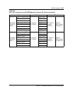
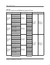
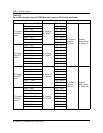
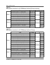
and the ATC for a 60° STSR configuration with two RF Frames and Table 3-
13 lists the connection between the PAs and the ATC for a 60° STSR
configuration with four RF Frames.