


3-2
Cell Site Layouts
411-2021-111 Standard 01.01 June 1996
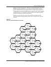
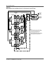
(ATC 1 and ATC 2) are combined through one phasing transformer (located at
ATC 2) and then connected to Duplexer position 2 and the main TX/RX
Antenna. The output of the upper ATC (ATC 3) is connected to Duplexer
position 3 and the diversity TX/RX Antenna. This arrangement is used to
meet the requirement of a minimum of 21 channel spacing (630 kHz)
between the channels in one RF Frame. This configuration requires a TX/RX
antenna to perform the diversity receive function of the cell. See Figure 3-3.
Control Channel redundancy
Control Channel (CCH) redundancy is commonly provided with a Locate
Channel Receiver (LCR) backup. The CCH is assigned to position 1 on the
TRU/DPA Shelf 1 and the LCR is assigned to position 4 on the same shelf.
This arrangement will have the CCH and the LCR supplied on a different DC
power feed and a TCM card. No RF coaxial switch is required since the
cavity of the LCR position on the ATC will tune to the CCH frequency when
backup is required.
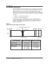
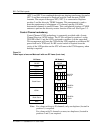
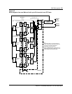
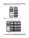
Figure 3-1
Frame layout of an omni Metrocell with one RF frame (front view)
Note:
For a frame with up to 20 channels, only one duplexer (located in
position 2) is required.
For a frame with 21 channels or more, two duplexers (located in
positions 2 and 3) are required.
CE RIP
DRUM
ACU
HSMO
CSM2
RMC 1
ICRM
Blank Panel
Base
Base
TRU/DPA
Shelf 1
ATC 1
Duplexer
Position 3
RF RIP
TRU/DPA
Shelf 2
ATC 2
TRU/DPA
Shelf 3
ATC 3
CE Frame RF Frame 1
Blank Panel
TRU 1
TRU 2
TRU 3
TRU 4
TRU 5
TRU 6
TRU 7
TRU 8
DPA
1
DPA
2
DPA
3
DPA
4
TRU 9
TRU 10
TRU 11
TRU 12
TRU 13
TRU 14
TRU 15
TRU 16
DPA
5
DPA
6
DPA
7
DPA
8
TRU 17
TRU 18
TRU 19
TRU 20
TRU 21
TRU 22
TRU 23
TRU 24
DPA
9
DPA
10
DPA
11
DPA
12
Duplexer
Position 1
Duplexer
Position 2