


Cell Site Configurations
2-3
DMS-MTX DualMode Metrocell Cell Site Description
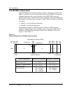
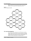
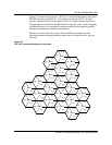
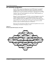
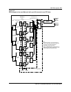
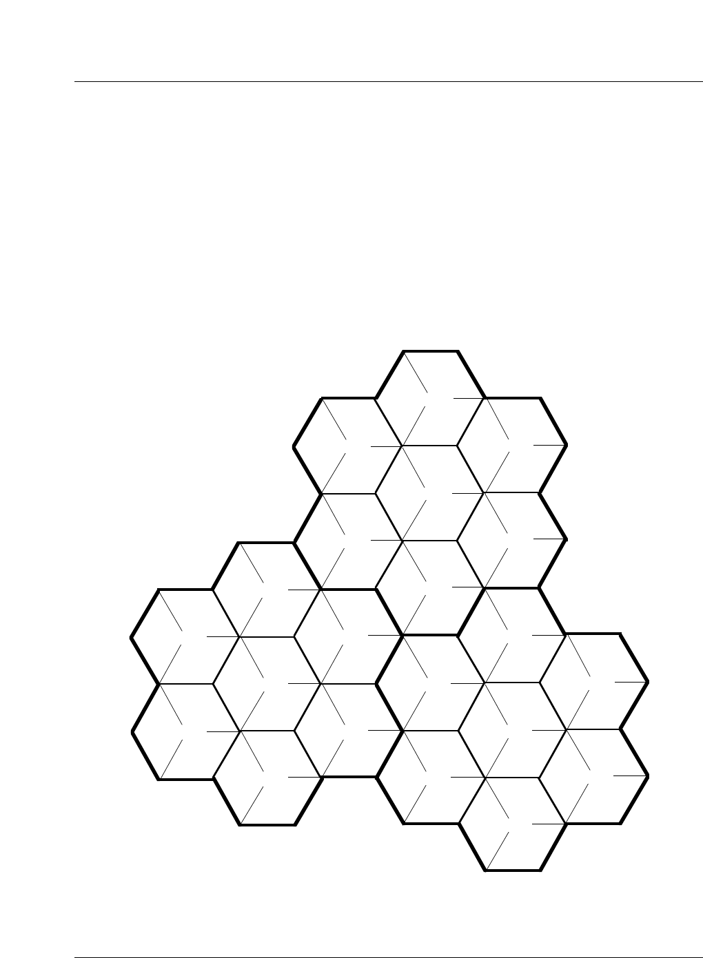
Figure 2-2 shows the layout of a 120
°
(N=7) sectorized frequency reuse plan.
The RF channels used in Cell 1 of a cluster are reused in Cell 1 of other
clusters, channels in Cell 2 are reused in Cell 2 of other clusters and so on.
This arrangement will have the RF channels using the same carrier frequency
in different areas to be separated from one another by the greatest possible
distance to minimize co-channel interference.
However, sectorization (by virtue of the modified coverage areas and
directional antenna usage) permits greater reuse of frequencies for a given
C/I ratio.
Figure 2-2
120
°
(N=7) sectorized frequency reuse plan
CELL 6
CELL 5
Sector
X
Sector
Y
Sector
Z
Sector
X
Sector
Y
Sector
Z
Sector
X
Sector
Y
Sector
Z
CELL 4
Sector
X
Sector
Y
Sector
Z
CELL 7
Sector
X
Sector
Y
Sector
Z
CELL 1
Sector
X
Sector
Y
Sector
Z
CELL 2
Sector
X
Sector
Y
Sector
Z
CELL 3
Sector
X
Sector
Y
Sector
Z
CELL 6
Sector
X
Sector
Y
Sector
Z
CELL 7
Sector
X
Sector
Y
Sector
Z
CELL 2
Sector
X
Sector
Y
Sector
Z
CELL 1
Sector
X
Sector
Y
Sector
Z
CELL 3
Sector
X
Sector
Y
Sector
Z
CELL 4
Sector
X
Sector
Y
Sector
Z
CELL 5
Sector
X
Sector
Y
Sector
Z
CELL 6
Sector
X
Sector
Y
Sector
Z
CELL 7
Sector
X
Sector
Y
Sector
Z
CELL 5
Sector
X
Sector
Y
Sector
Z
CELL 1
Sector
X
Sector
Y
Sector
Z
CELL 2
Sector
X
Sector
Y
Sector
Z
CELL 3
Sector
X
Sector
Y
Sector
Z
CELL 4