


Cell Site Layouts
3-17
DMS-MTX DualMode Metrocell Cell Site Description
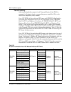
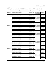
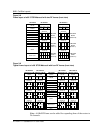
Receive cabling
In the reverse path, the receive signal from the main antenna of each sector is
connected to the A-input of the Receive Multicoupler (RMC) through the
receive port of the duplexer of that sector. The diversity antenna connects
directly to the B-input of the RMC. Distribution of the reverse path
frequencies is accomplished by RF splitters within each RF frame.
Table 3-8 lists the connection between the RMCs and the RF splitters in a
120
°
STSR Metrocell with one RF Frame. Table 3-9 lists the connection
between the RMCs and the RF splitters in a 120
°
STSR Metrocell using three
RF frames.
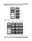
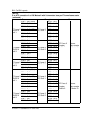
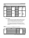
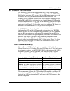
RF Frame 3
TRU/DPA
Shelf 2
DPA 6 - Port2 RF Frame 3
ATC Shelf 2
ATC2 - Port 4 RF Frame 3
Duplexer
Position 2
Antenna
(Main receive
for Sector Z)
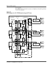
DPA 7 - Port1 ATC2 - Port 5
DPA 7 - Port 2 ATC2 - Port 6
DPA 8 - Port1 ATC2 - Port 7
DPA 8 - Port 2 ATC2 - Port 8
DPA 9 - Port1 ATC3 - Port 1
DPA 9 - Port 2 ATC3 - Port 2
DPA 10 - Port1 ATC3 - Port 3
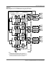
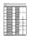
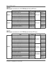
RF Frame 3
TRU/DPA
Shelf 3
DPA 10 - Port2 RF Frame 3
ATC Shelf 3
ATC3 - Port 4 RF Frame 3
Duplexer
Position 3
Antenna
(Diversity
receive for
Sector Z)
DPA 11- Port1 ATC3 - Port 5
DPA 11- Port 2 ATC3 - Port 6
DPA 12 - Port1 ATC3 - Port 7
DPA 12 - Port2 ATC3 - Port 8
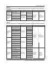
Table 3-8
RMC to splitter connections for a 120
°
STSR Metrocell with one RF Frame
From Through To
Main antenna, Sector X RMC 1A - A1 Splitter 1
Main antenna, Sector Y RMC 2A - A1 Splitter 2
Sector X
Main antenna, Sector Z RMC 3A - A1 TRU shelf 1 Splitter 3
Diversity antenna, Sector X RMC 1B - B1 Splitter 4
Diversity antenna, Sector Y RMC 2B - B1 Splitter 5
Diversity antenna, Sector Z RMC 3B - B1 Splitter 6
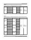
Table 3-7
PA to ATC connection for a 120
°
Metrocell with 21 channels or more per RF frame for one sector
(continued)
From Through To