


3-6
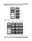
Cell Site Layouts
411-2021-111 Standard 01.01 June 1996
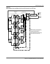
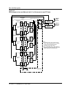
Note:
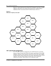
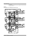
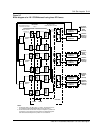
Additional RF Frames with 21 channels or more are connected to
their respective TX/RX antennas in the same way as RF Frame 1.
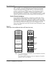
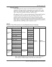
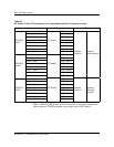
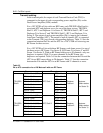
Table 3-2
RF Frame 1 PA to ATC connection for an omni Metrocell with 21 channels or more
From Through To
DPA 1 - Port1 (CCH) ATC1 - Port 1
DPA 1 - Port2 ATC1 - Port 2
DPA 2 - Port1 ATC1 - Port 3
TRU/DPA
Shelf 1
DPA 2 - Port2 (LCH) ATC Shelf 1 ATC1 - Port 4
DPA 3 - Port1 ATC1 - Port 5
DPA 3 - Port2 ATC1 - Port 6
DPA 4 - Port1 ATC1 - Port 7
DPA 4 - Port2 ATC1 - Port 8 Duplexer
Position 2
Antenna
(Main receive)
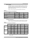
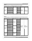
DPA 5 - Port1 ATC2 - Port 1
DPA 5 - Port2 ATC2 - Port 2
DPA 6 - Port1 ATC2 - Port 3
TRU/DPA
Shelf 2
DPA 6 - Port2 ATC Shelf 2 ATC2 - Port 4
DPA 7 - Port1 ATC2 - Port 5
DPA 7 - Port 2 ATC2 - Port 6
DPA 8 - Port1 ATC2 - Port 7
DPA 8 - Port 2 ATC2 - Port 8
DPA 9 - Port1 ATC3 - Port 1
DPA 9 - Port 2 ATC3 - Port 2
DPA 10 - Port1 ATC3 - Port 3
TRU/DPA
Shelf 3
DPA 10 - Port2 ATC Shelf 3 ATC3 - Port 4 Duplexer
Position 3
Antenna
(Diversity
receive)
DPA 11 - Port1 ATC3 - Port 5
DPA 11 - Port 2 ATC3 - Port 6
DPA 12 - Port1 ATC3 - Port 7
DPA 12 - Port2 ATC3 - Port 8