


Cell Site Layouts
3-21
DMS-MTX DualMode Metrocell Cell Site Description
60
°
STSR cell site connection
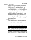
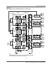
The Metrocell in a 60
°
STSR configuration uses at least three equipment
frames, one CE Frame and two RF frames (see Figure 3-8). Each TRU/DPA
Shelf and its associated ATC on one of the two RF frames support one of the
six sectors. With only two RF frames, the maximum number of Voice
Channels (VCH) supported by each sector is six since two of the eight TRUs
on the TRU shelf have to be assigned as the Control Channel (CCH) and the
Locate Channel Receiver (LCR). A 60
°
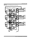
STSR Metrocell with two RF Frames
requires twelve antennas; one TX/RX antenna and one RX only antenna for
each sector (see Figure 3-10). As traffic grows, two additional RF frames can
be added to accommodate more VCHs per sector (see Figure 3-9).
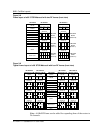
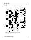
A 60
°
STSR Metrocell with four RF Frames has 16 channels for one sector
(including the CCH and the LCR) and each sector requires two TRU/DPA
shelves and two ATCs. It also requires twelve antennas; one TX/RX antenna
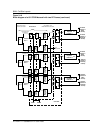
and one RX only antenna for each sector. The outputs of the two ATCs for
each sector are combined through one phasing transformer and connected to a
duplexer. The output of duplexer is then connected to the main TX/RX
Antenna of that sector. The diversity RX antenna of each sector is connected
directly to the Receive Multicoupler (RMC) of that sector. Figure 3-9 shows
the frame layout and Figure 3-11 shows the block diagram of a 60
°
STSR
Metrocell with four RF Frames.
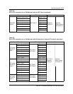
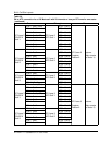
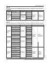
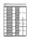
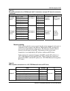
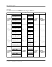
Control Channel redundancy
Control Channel (CCH) redundancy is commonly provided with a Locate
Channel Receiver (LCR) backup. With two RF Frames, the CCH of each sector
is assigned to position 1 on the TRU/DPA Shelf of that sector and the LCR is
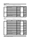
assigned to position 4 on the same shelf. With four RF Frames, a typical
assignment of the CCH and LCR for each sector is listed below:
This arrangement will have the CCH and the LCR supplied on a different DC
power feed and a TCM card. No RF coaxial switch is required since the
cavity of the LCR position on the ATC will tune to the CCH frequency when
backup is required.
Control Channel Locate Channel Receiver
Sector X
RF Frame 1/TRU Shelf 1/Position 1 RF Frame 1/TRU Shelf 1/Position 4
Sector Y
RF Frame 2/TRU Shelf 1/Position 1 RF Frame 2/TRU Shelf 1/Position 4
Sector Z
RF Frame 2/TRU Shelf 3/Position 1 RF Frame 2/TRU Shelf 3/Position 4
Sector U
RF Frame 3/TRU Shelf 1/Position 1 RF Frame 3/TRU Shelf 1/Position 4
Sector V
RF Frame 4/TRU Shelf 1/Position 1 RF Frame 4/TRU Shelf 1/Position 4
Sector W
RF Frame 3/TRU Shelf 3/Position 1 RF Frame 3/TRU Shelf 3/Position 4