


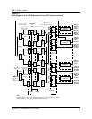

3-22
Cell Site Layouts
411-2021-111 Standard 01.01 June 1996
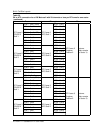
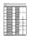
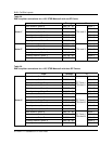
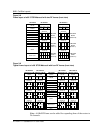
Figure 3-8
Frame layout of a 60
°
STSR Metrocell with two RF frames (front view)
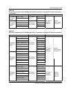
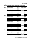
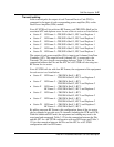
Figure 3-9
Typical frame layout of a 60
°
STSR Metrocell with four RF frames (front view)
Note:
A fifth RF Frame can be added for expanding three of the sectors to
24 channels.
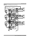
CE Frame RF Frame 1
CE RIP
DRUM
ACU
HSMO
CSM 2
RMC 1 (Sector X)
ICRM
Blank Panel
Base
RMC 2 (Sector Y)
RMC 3 (Sector Z)
TRU/DPA
Shelf 1
(Sector X)
TRU/DPA
Shelf 2
(Sector Y)
TRU/DPA
Shelf 3
(Sector Z)
Base
ATC 1
(Sector X)
Duplexer
(Sector Y)
RF RIP
ATC 2
(Sector Y)
ATC 3
(Sector Z)
TRU 1
TRU 2
TRU 3
TRU 4
TRU 5
TRU 6
TRU 7
TRU 8
DPA
1
DPA
2
DPA
3
DPA
4
TRU 9
TRU 10
TRU 11
TRU 12
TRU 13
TRU 14
TRU 15
TRU 16
DPA
5
DPA
6
DPA
7
DPA
8
TRU 17
TRU 18
TRU 19
TRU 20
TRU 21
TRU 22
TRU 23
TRU 24
DPA
9
DPA
10
DPA
11
DPA
12
Duplexer
(Sector Z)
Duplexer
(Sector X)
RF Frame 2
TRU/DPA
Shelf 1
(Sector U)
TRU/DPA
Shelf 2
(Sector V)
TRU/DPA
Shelf 3
(Sector W)
Base
ATC 1
(Sector U)
Duplexer
(Sector V)
RF RIP
ATC 2
(Sector V)
ATC 3
(Sector W)
TRU 1
TRU 2
TRU 3
TRU 4
TRU 5
TRU 6
TRU 7
TRU 8
DPA
1
DPA
2
DPA
3
DPA
4
TRU 9
TRU 10
TRU 11
TRU 12
TRU 13
TRU 14
TRU 15
TRU 16
DPA
5
DPA
6
DPA
7
DPA
8
TRU 17
TRU 18
TRU 19
TRU 20
TRU 21
TRU 22
TRU 23
TRU 24
DPA
9
DPA
10
DPA
11
DPA
12
Duplexer
(Sector W)
Duplexer
(Sector U)
RMC 4 (Sector U)
RMC 5 (Sector V)
RMC 6 (Sector W)
Position 1Position 2Position 3 Position 1Position 2Position 3
CE Frame
RF Frame 1
(Sectors X & Z)
CE RIP
DRUM
ACU
HSMO
CSM 2
RMC 1 (Sector X)
ICRM
Blank Panel
Base
RMC 2 (Sector Y)
RMC 3 (Sector Z)
Base
ATC 1
(Sector X)
RF RIP
ATC 2
(Sector X)
TRU 1
TRU 2
TRU 3
TRU 4
TRU 5
TRU 6
TRU 7
TRU 8
DPA
1
DPA
2
DPA
3
DPA
4
TRU 9
TRU 10
TRU 11
TRU 12
TRU 13
TRU 14
TRU 15
TRU 16
DPA
5
DPA
6
DPA
7
DPA
8
Duplexer
(Sector Z)
RF Frame 2
(Sectors Y & Z)
Base
ATC 1
(Sector Y)
RF RIP
ATC 2
(Sector Y)
TRU 1
TRU 2
TRU 3
TRU 4
TRU 5
TRU 6
TRU 7
TRU 8
DPA
1
DPA
2
DPA
3
DPA
4
TRU 9
TRU 10
TRU 11
TRU 12
TRU 13
TRU 14
TRU 15
TRU 16
DPA
5
DPA
6
DPA
7
DPA
8
Duplexer
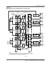
RMC 4 (Sector U)
RMC 5 (Sector V)
RMC 6 (Sector W)
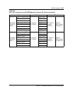
RF Frame 4
(Sectors V & W)
Base
ATC 1
(Sector V)
RF RIP
ATC 2
(Sector V)
TRU 1
TRU 2
TRU 3
TRU 4
TRU 5
TRU 6
TRU 7
TRU 8
DPA
1
DPA
2
DPA
3
DPA
4
TRU 9
TRU 10
TRU 11
TRU 12
TRU 13
TRU 14
TRU 15
TRU 16
DPA
5
DPA
6
DPA
7
DPA
8
RF Frame 3
(Sectors U & W)
Base
ATC 1
(Sector U)
RF RIP
ATC 2
(Sector U)
TRU 1
TRU 2
TRU 3
TRU 4
TRU 5
TRU 6
TRU 7
TRU 8
DPA
1
DPA
2
DPA
3
DPA
4
TRU 9
TRU 10
TRU 11
TRU 12
TRU 13
TRU 14
TRU 15
TRU 16
DPA
5
DPA
6
DPA
7
DPA
8
ATC 3
(Sector Z)
ATC 3
(Sector Z)
Duplexer
(Sector X)
(Sector X)
(Sector X)
(Sector Y)
(Sector Y)
TRU 17
TRU 18
TRU 19
TRU 20
TRU 21
TRU 22
TRU 23
TRU 24
DPA
9
DPA
10
DPA
11
DPA
12
(Sector Z)
TRU 17
TRU 18
TRU 19
TRU 20
TRU 21
TRU 22
TRU 23
TRU 24
DPA
9
DPA
10
DPA
11
DPA
12
(Sector Z)
ATC 3
(Sector W)
ATC 3
(Sector W)
TRU 17
TRU 18
TRU 19
TRU 20
TRU 21
TRU 22
TRU 23
TRU 24
DPA
9
DPA
10
DPA
11
DPA
12
(Sector W)
TRU 17
TRU 18
TRU 19
TRU 20
TRU 21
TRU 22
TRU 23
TRU 24
DPA
9
DPA
10
DPA
11
DPA
12
(Sector W)
(Sector V)
(Sector V)
(Sector U)
(Sector U)
Duplexer
(Sector Y)
DuplexerDuplexer
Position 1Position 2Position 3Position 1Position 2Position 3
Duplexer
(Sector W)
DuplexerDuplexer
(Sector V)
Duplexer
(Sector U)
DuplexerDuplexer
Position 1Position 2Position 3Position 1Position 2Position 3