


3-4
Cell Site Layouts
411-2021-111 Standard 01.01 June 1996
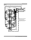
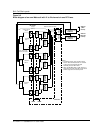
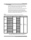
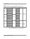
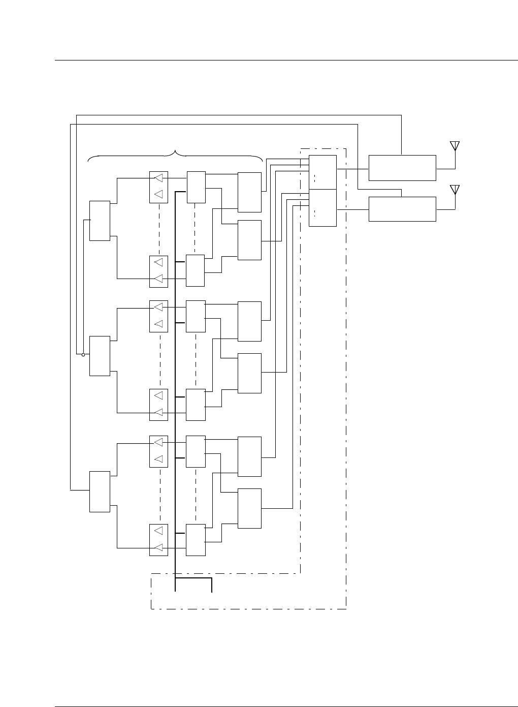
Figure 3-3
Block diagram of an omni Metrocell with 21 to 24 channels in one RF Frame
TRU 1
6 5 4 3 2 1
TRU SHELF
SPLITTER 1
TRU SHELF
SPLITTER 4
ICRM HSMO
RF Frame 1
TRU 8
6 5 4 3 2 1
TRU 9
6 5 4 3 2 1
TRU 16
6 5 4 3 2 1
Duplexer
Position 2
RX ANT
TX
B1
B2
B8
A1
A2
A8
RMC 1A
RMC 1B
Antenna
(Main
receive)
Antenna
(Diversity
receive)
(Note 1)
See Table 3-3 for
RMC/TRU Shelf connection
Notes:
1.
2.
For diagram clarity, only one RF Frame is
shown. Other RF Frames with 21 channels
or mor are connected and operated
identically to that of RF Frame 1.
TRU1 at TRU/DPA Shelf 1 of RF Frame 1 is
assigned as the CCH and TRU4 at the same
shelf is assigned as the backup CCH.
TRU SHELF
SPLITTER 1
TRU SHELF
SPLITTER 4
TRU/DPA
Shelf 1
TRU/DPA
Shelf 2
ATC 1
ATC 2
See Table 3-2 for
PA/ATC connection
Control Channel
(Note 2)
CE Frame
TRU 17
6 5 4 3 2 1
TRU 24
6 5 4 3 2 1
TRU SHELF
SPLITTER 1
TRU SHELF
SPLITTER 4
TRU/DPA
Shelf 3
ATC 3
A3
B3
DPA 12
DPA 9
DPA 1
DPA 4
DPA 5
DPA 8
Duplexer
Position 3
RX ANT
TX