


6-6
Datafilling a Metro Cell Site
411-2021-111 Standard 01.01 June 1996
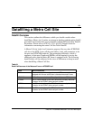
Frequency Assignment Example
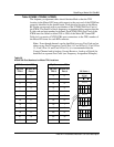
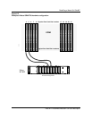
An example configuration is shown in Figure 6-1. In this example The ICRM
virtual port card 0 is hardwired to the RIP Connector J205 and virtual port
card 1 is hardwired to RIP Connector J206 (see Figure 6-2). Since port card 0
is hardwired to J205 it will be connected to all the TRUs with odd numbered
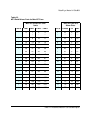
Metro locations (Refer to the Metro RF Frame Figure for the TRU numbering
scheme). Hence port card 1, which is hardwired to J206, will be connected to
all the TRUs with even numbered Metro locations.
Five datafill tuples are shown in the example figure for:
• a CCH,
• a Digital Locate Receiver (DLR)—serving as the CCH backup in this
example,
• an Analog Locate Receiver (ALR)—can be assigned to any TRU, and
• two VCH TRU personalities.
The table in the figure shows the location of the five TRUs with respect to
their Metro shelf locations.
Figure 6-1
Example of Metro TRU datafill
Note:
J205 and J206 are cabled to the ICRM port cards as shown in Figure 6-2.
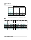
Table CCHINV
CCHKEY CHANNO BACKUP MODE TERMATTR CARD PORT ALRAMPT
49 0 331 Y 0 AUTOTUNE COMBINED TRU2AN60 0 0 0
Table LCRINV
LCRKEY CCHBACKED ADMODE TERMATTR CARD PORT ALARMPT LCRTEST
49 0 Y 0 TDMA3 TRU2AN60 1 1 1 N
49 1 N ANALOG TRU2AN60 1 2 2 N
Table VCHINV
VCHKEY CHANNO ADMODE GROUP TRKMEMS TERMATTR CARD PORT ALARMPT XCVRSAT
49 1 289 TDMA3 (000) (1)(101)(201) TRU2AN60 0 1 1 DEFAULT
49 4 226 ANALOG_TDMA3 (001) (4)(104)(204) TRU2AN60 1 3 4 DEFAULT
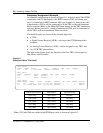
Channel and Frequency ICRM location RF Frame location
TRU Slot 1CCH 0 (331)
LCR 0 (DLR)
LCR 1 (ALR)
VCH 1 (289)
VCH 4 (226)
Card 0 Port 0
Card 1 Port 1
Card 1 Port 2
Card 0 Port 1
Card 1 Port 3
TRU Slot 4
TRU Slot 6
TRU Slot 3
TRU Slot 8