


Cell Site Layouts
3-7
DMS-MTX DualMode Metrocell Cell Site Description
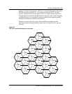
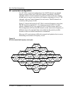
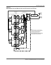
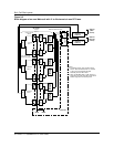
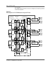
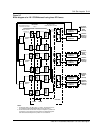
Receive cabling
In the reverse path, the receive signal from the main antenna is connected to
the A-input of the Receive Multicoupler (RMC) through the receive port of
the duplexer. The diversity antenna connects directly to the B-input of the
RMC. Distribution of the reverse path frequencies is accomplished by RF
splitters within each RF frame.
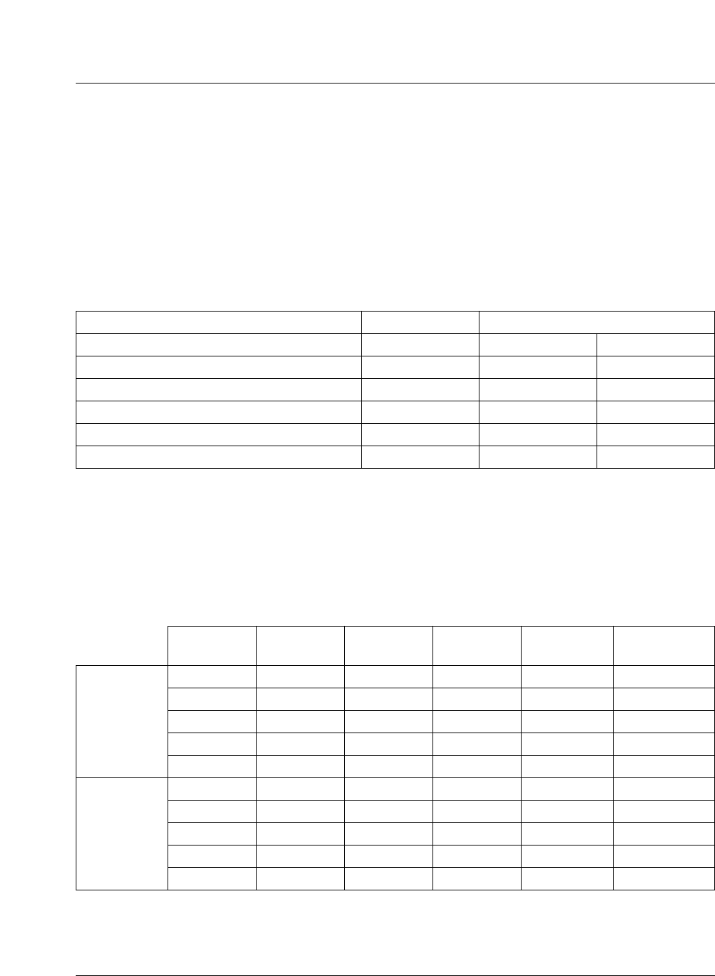
Table 3-3 shows the connection between the RMC and the splitters.
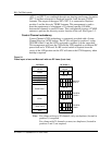
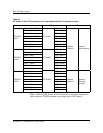
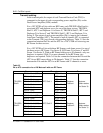
Component requirement
Table 3-4 lists the components required for a Metrocell with one to five RF
Frames. An omni cell site requires only one Receive Multicoupler (RMC).
Note:
An additional TCM port card is required for the DRUM, the ACU
and the CSM2.
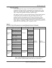
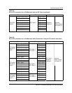
Table 3-3
RMC to splitter connections for an Omni Metrocell
From Through To
Main antenna RMC 1A - A1 TRU Shelf 1 Splitter 1
Diversity antenna RMC 1B - B1 TRU Shelf 1 Splitter 4
Main antenna RMC 1A - A2 TRU Shelf 2 Splitter 1
Diversity antenna RMC 1B - B2 TRU Shelf 2 Splitter 4
Main antenna RMC 1A - A3 TRU Shelf 3 Splitter 1
Diversity antenna RMC 1B - B3 TRU Shelf 3 Splitter 4
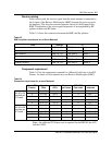
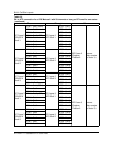
Table 3-4
Component requirement for an omni Metrocell
No. of RF
Frames
No. of
TRUs
No. of
ATCs
Duplexer
per frame
ICRM TCM
Port cards
No. of
antennas
Configuration
with up to 20
channels per
RF Frame
1 3 to 20 1 to 3 1 2 1 TX/RX, 1 RX
2 21 to 40 4 to 6 1 4 2 TX/RX
3 41 to 60 7 to 9 1 6 2 TX/RX, 1 TX
4 61 to 80 10 to 12 1 6 2 TX/RX, 2 TX
5 81 to 100 13 to 15 1 8 2 TX/RX, 3 TX
Configuration
with up to 24
channels per
RF Frame
1 3 to 24 1 to 3 2 2 2 TX/RX
2 25 to 48 4 to 6 2 4 2 TX/RX, 2 TX
3 49 to 72 7 to 9 2 6 2 TX/RX, 4 TX
4 73 to 96 10 to 12 2 6 2 TX/RX, 6 TX
5 97 to 120 13 to 15 2 8 2 TX/RX, 8 TX