


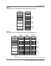

Cell Site Layouts
3-5
DMS-MTX DualMode Metrocell Cell Site Description
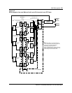
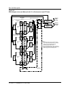
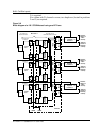
Transmit cabling
In the transmit path, the output of each Transmit Receive Unit (TRU) is
connected to the input of each corresponding power amplifier (PA) on the
Dual Power Amplifier (DPA) module. The output of each power amplifier
(PA) is input to an 8-channel AutoTune Combiner (ATC).
The output of the ATC is connected to the Transmit (TX) port of the duplexer.
For RF Frames using more than one ATC, the outputs of the ATCs are
combined together and connected to the TX port of the duplexer. The
duplexer serves as the interface between the antenna system and the RF
frame. Table 3-1 lists the connection between the PAs and the ATC for an RF
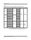
Frame with up to 20 channels. Table 3-2 lists the connection between the PAs
and the ATC for an RF Frame with 21 channels or more.
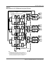
Note:
Additional RF Frames with 20 channels or less are connected to
their respective TX/RX antennas in the same way as RF Frame 1.
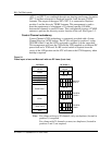
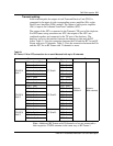
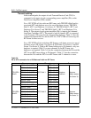
Table 3-1
RF Frame 1 PA to ATC connection for an omni Metrocell with up to 20 channels
From Through To
DPA 1 - Port1 (CCH) ATC1 - Port 1
DPA 1 - Port2 ATC1 - Port 2
DPA 2 - Port1 ATC1 - Port 3
TRU/DPA
Shelf 1
DPA 2 - Port2 (LCH) ATC Shelf 1 ATC1 - Port 4
DPA 3 - Port1 ATC1 - Port 5
DPA 3 - Port2 ATC1 - Port 6
DPA 4 - Port1 ATC1 - Port 7
DPA 4 - Port2 ATC1 - Port 8
DPA 5 - Port1 ATC2 - Port 1
DPA 5 - Port2 ATC2 - Port 2 Duplexer
Position 2
Antenna
(Main receive)
DPA 6 - Port1 ATC2 - Port 3
TRU/DPA
Shelf 2
DPA 6 - Port2 ATC Shelf 2 ATC2 - Port 4
DPA 7 - Port1 ATC2 - Port 5
DPA 7 - Port 2 ATC2 - Port 6
DPA 8 - Port1 ATC2 - Port 7
DPA 8 - Port 2 ATC2 - Port 8
DPA 9 - Port1 ATC3 - Port 1
TRU/DPA
Shelf 3
DPA 9 - Port 2 ATC Shelf 3 ATC3 - Port 2
DPA 10 - Port1 ATC3 - Port 3
DPA 10 - Port2 ATC3 - Port 4