


6-2
Datafilling a Metro Cell Site
411-2021-111 Standard 01.01 June 1996
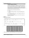
Table CLLI
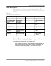
Table CLLI defines both a name and a quantity to a certain MTX trunk
assignment. For the Metro application the number of trunks assigned in
TRKGRSIZ should be capable of supporting the additional VCHs supported.
The minimum number of trunks required is shown in Table 6-2 for various
Metro configurations with the maximum number of DRUs.
Note:
It is a good practice to assign more trunks than is necessary to
prevent from having to backtrack through all the Tables to change the
number in Table CLLI.
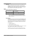
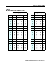
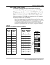
Table ACUALM
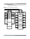
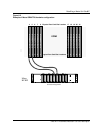
A Metrocell has input alarm points hardwired to the ACU. The alarm points
for the CE Frame remain the same as per the standard NT800DR Macro Cell
Site although their numbering scheme is changed. However the Metro RF
Frame alarm points differ. The alarm point configuration for each Metro RF
Frame has 23 alarm points to be datafilled in Table ACUALM. The alarm
points monitor the:
• TRU/DPA cooling fans
• A and B side DC power filters
• ATC: cavities, DC power, and cooling fan
The alarm points are also assigned for each DRU in the frequency assignment
tables (CCHINV, LCRINV, VCHINV) of the Metro Cell Site.
The MTX alarm point numbers for the hardwired Metro RF frame alarm
points are listed in Table 6-3 and Table 6-4 for the MTX Table ACUALM.
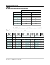
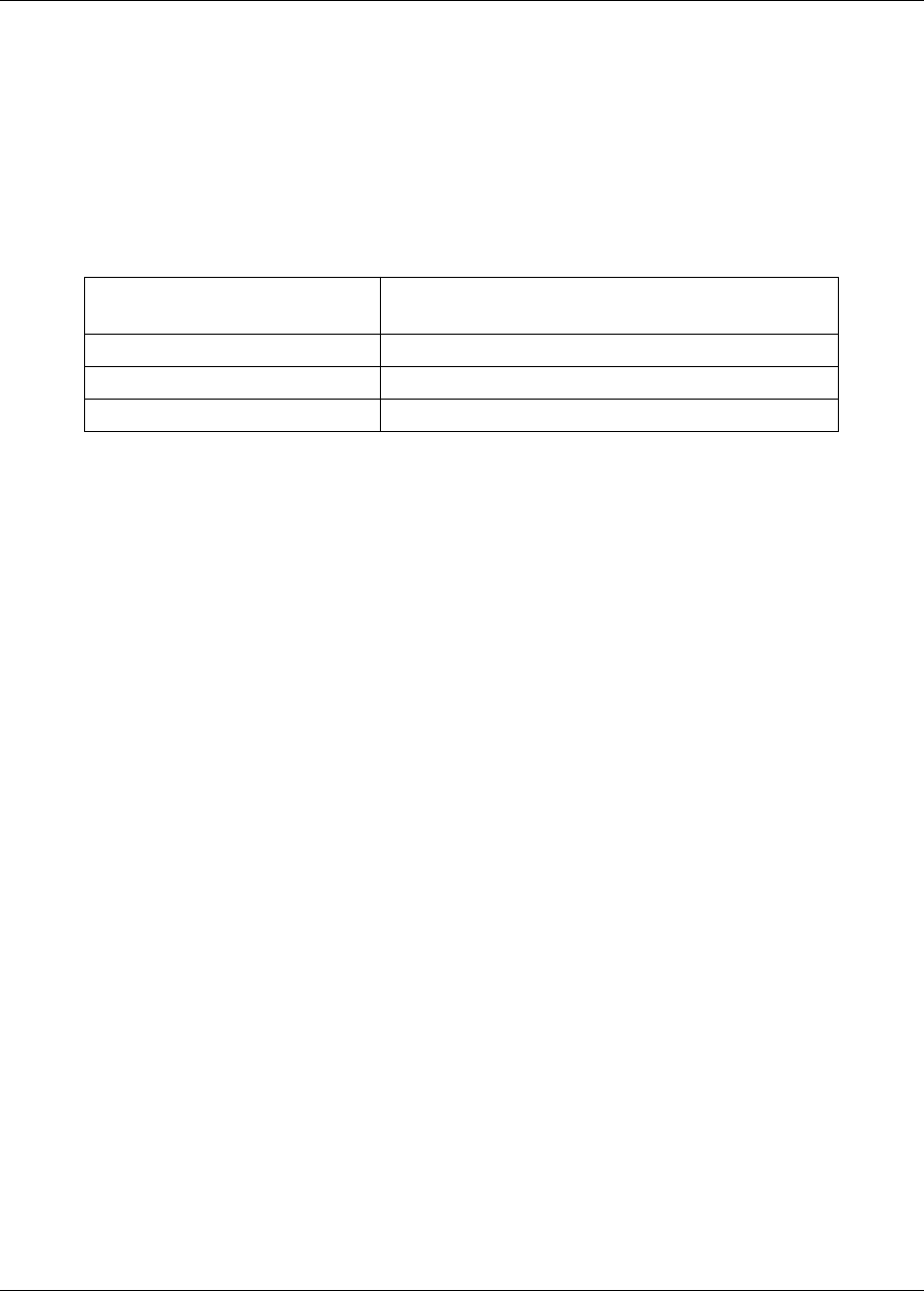
Table 6-2
Trunk requirement for different Metrocell configurations
Metro Site Type Minimum Number of Trunks assigned to Table
CLLI field TRKGRSIZ
Omni site 24
120 Sectored (1 RF Frame) 24
60 Sectored (2 RF Frames) 48