


Cell Site Layouts
3-11
DMS-MTX DualMode Metrocell Cell Site Description
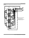
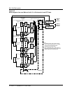
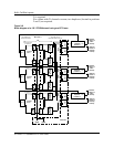
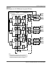
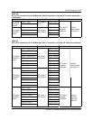
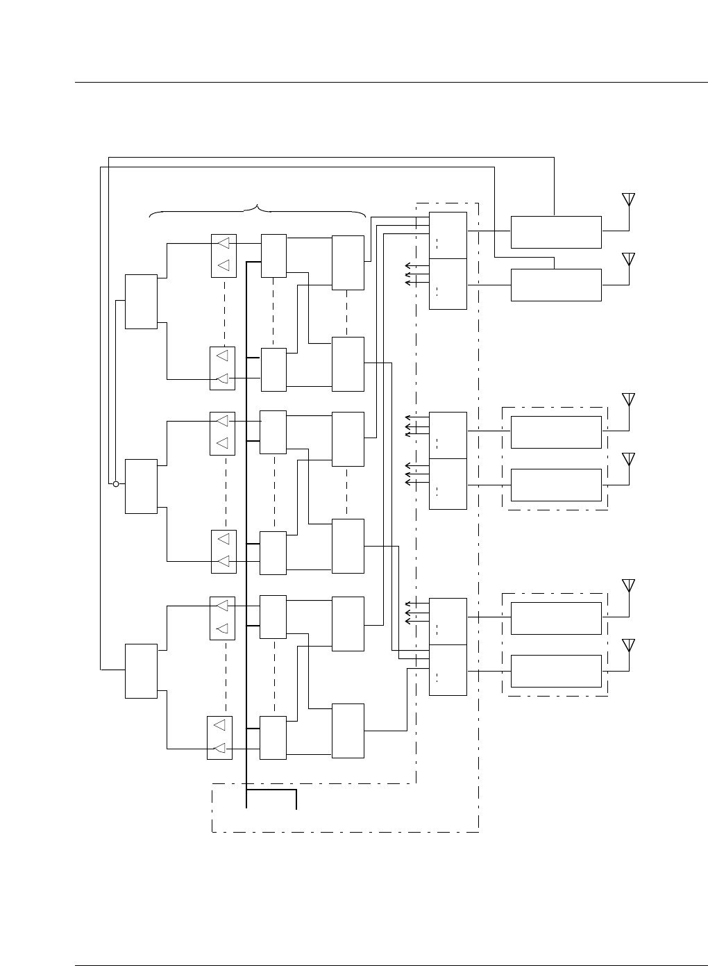
Figure 3-7
Block diagram of a 120
°
STSR Metrocell using three RF Frames
Notes:
1.
2.
For diagram clarity, only RF Frame 1 is shown. RF Frames 2 and 3
are connected and operated identically to that of RF Frame 1.
For RF Frames with 20 channels or less, the Duplexer in position 3 is
not required. The outputs of the three ATCs are combined together
and connected to the Duplexer in position 2. See Table 3-6.
TRU 1
6 5 4 3 2 1
TRU SHELF
SPLITTER 1
TRU SHELF
SPLITTER 6
ICRM HSMO
RF Frame 1
Note 1
TRU 8
6 5 4 3 2 1
TRU 9
6 5 4 3 2 1
TRU 16
6 5 4 3 2 1
Duplexer
Position 2
RX ANT
TX
B1
B2
B8
A1
A2
A8
RMC 1A
RMC 1B
Antenna
(Sector X
Main
receive)
Antenna
(Sector X
Diversity
receive)
See Table 3-9 for
RMC/TRU Shelf connection
TRU SHELF
SPLITTER 1
TRU SHELF
SPLITTER 6
TRU/DPA
Shelf 1
TRU/DPA
Shelf 2
ATC 1
ATC 2
See Tables 3-6 and 3-7
for PA/ATC connection
Control Channel
for Sector X
CE Frame
TRU 17
6 5 4 3 2 1
TRU 24
6 5 4 3 2 1
TRU SHELF
SPLITTER 1
TRU SHELF
SPLITTER 6
TRU/DPA
Shelf 3
ATC 3
A3
B3
B1
B2
B8
A1
A2
A8
RMC 2A
RMC 2B
Antenna
(Sector Y
Main
receive)
Antenna
(Sector Y
Diversity
receive)
A3
B3
B1
B2
B8
A1
A2
A8
RMC 3A
RMC 3B
Antenna
(Sector Z
Main
receive)
Antenna
(Sector Z
Diversity
receive)
A3
B3
DPA 12
DPA 1
DPA 4
DPA 5
DPA 8
DPA 9
Duplexer
Position 3
RX ANT
TX
Duplexer
Position 3
RX ANT
TX
Duplexer
Position 2
RX ANT
TX
RF Frame 2
Duplexer
Position 3
RX ANT
TX
Duplexer
Position 2
RX ANT
TX
RF Frame 3
Note 2