


Section II - Description
Quincy Compressor
®
- QSD™ 9
• General Description
• The Compression Cycle
• Cooling System
• Lubricating Fluid System
• Moisture Separator
• Capacity Control System
• Electrical System
• Indicators
General Description
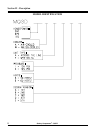
The QSD
™
compressor is a two-stage, positive
displacement, oil-free rotary screw unit consisting of two
precision-machined rotors per stage. The male rotor of
each stage are turned by a set of precision timing gears
which are driven by the motor through a flexible drop-out
type coupling. Both rotors (of each stage) are housed in a
single cast iron cylinder with water jackets surrounding
them.
All models are equipped with a positive displacement
fluid pump mounted to the gearbox to circulate fluid
through the bearing system and to the gear mesh. The
fluid cooler, fluid pressure relief valve, and fluid filter are
also mounted on the gearbox.
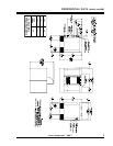
All components are attached to a heavy-duty steel frame.
Controls and indicators are arranged on a control panel.
An acoustical cabinet is included to reduce machine
sound levels.
The Compression Cycle and Air Flow
The compression cycle of the two-stage QSD
™
rotary
compressor is a continuous process from the intake of
stage one to the discharge of stage two. Each stage
consists of two rotors in constant mesh, housed in a
cylinder with two parallel adjoining bores. Each male
rotor has lobes that mesh with flutes in the female rotor.
The rotors are synchronized via AGMA12 timing gears.
All parts are machined to exacting tolerances.
As the rotors of stage one rotate, air is drawn into the
cylinder through the inlet port located immediately after
the air cleaner connection. A volume of air is trapped as
the rotor lobes pass the inlet cut off points in the
cylinders. Compression occurs as the male rotor rolls
into the female flute, progressively reducing the space,
thereby raising the pressure.
Compression continues until the lobe and flute pass the
discharge port. The compressed air is then discharged
into the intercooler. The air then flows through a
moisture separator/trap assembly to remove condensate
from the cooling process. From there the air flows to the
inlet of stage two. Air inlet pressure at the stage two inlet
should be between 30 to 36 psig.
In stage two, the above compression process is repeated.
Discharge air pressure from stage two will be the
requested system pressure. From stage two the
compressed air travels through an aftercooler and a
second moisture separator/trap assembly. The
compressed air passes through a minimum pressure
check valve and into the compressed air distribution
system.