


Section VIII - Power$ync II
™
Operation
58 Quincy Compressor
®
- QSD™
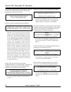
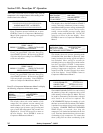
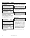
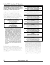
Press the UP key to advance to the next menus (shown
below) or ENTER to exit.
**STAGE 1 DISCH. PRESSURE TRANSDUCER**
A/D CONVERTER READING______ OFFSET______
COMPUTED PRESSURE READING______
UP FOR NEXT MENU/DOWN FOR PREVIOUS MENU
**STAGE 2 DISCH. PRESSURE TRANSDUCER**
A/D CONVERTER READING______ OFFSET______
COMPUTED PRESSURE READING______
UP FOR NEXT MENU/DOWN FOR PREVIOUS MENU
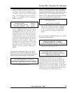
**FLUID PRESSURE TRANSDUCER**
A/D CONVERTER READING______ OFFSET______
COMPUTED PRESSURE READING______
UP FOR NEXT MENU/DOWN FOR PREVIOUS MENU
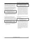
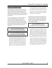
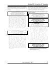
The following menus show temperature probe
information. These readings are more difficult to utilize,
as the RTD probes are resistance devices, whose signals
are processed before input to the A/D converter. Of more
interest will be the OFFSET values. If these values are
off by a large amount or show a variance in one RTD, a
potential fault could be indicated.
**PACKAGE DISCH. RTD TRANSDUCER **
A/D CONVERTER READING______ OFFSET______
COMPUTED PRESSURE READING______
UP FOR NEXT MENU/DOWN FOR PREVIOUS MENU
**STAGE 1 DISCH. RTD TRANSDUCER**
A/D CONVERTER READING______ OFFSET______
COMPUTED PRESSURE READING______
UP FOR NEXT MENU/DOWN FOR PREVIOUS MENU
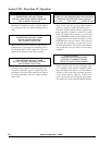
**STAGE 2 INPUT RTD TRANSDUCER**
A/D CONVERTER READING______ OFFSET______
COMPUTED PRESSURE READING______
UP FOR NEXT MENU/DOWN FOR PREVIOUS MENU
**STAGE 2 DISCH. RTD TRANSDUCER**
A/D CONVERTER READING______ OFFSET______
COMPUTED PRESSURE READING______
UP FOR NEXT MENU/DOWN FOR PREVIOUS MENU
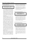
Press ENTER to return to the Compressor
Diagnostic Menu.
Press ENTER to return to Compressor Maintenance
Menu 3, and press the UP key to advance to Compressor
Maintenance Menu 4.
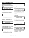
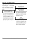
**
COMPRESSOR MAINTENANCE MENU 4**
EDIT MODEM INIT SEQUENCE ➔ PRESS F1
CLEAR MUFFLER FLAGS ➔ PRESS F2
UP FOR NEXT MENU/DOWN FOR PREVIOUS MENU
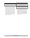
Press F1 to enter the MODEM INIT SEQUENCE
editor. This menu should not require any adjusting,
as it has been configured at the factory for the
modem being used.
**MODEM INITIALIZATION**
INIT:
ATE0&D2S0=1&E3&RD1&C4#F0$R1&E12$E14&E1
* F1 TO EDIT/ENTER TO ACCEPT VALUE
Press ENTER to exit this menu.
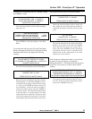
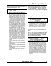
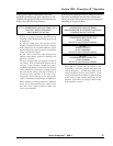
From Compressor Maintenance Menu 4, press F2 to enter
the muffler flag menu.
CLEAR WARNINGS ON MUFFLER BACK PRESSURE
RESET FLAG ON INTERSTAGE BLOWDOWN ➔ F1
RESET FLAG ON STG. 2 BLOWDOWN ➔ F2
**PRESS ENTER TO RETURN**
This menu is used to cancel the flag set by the
detection of residual pressure during blowdown
when the compressor unloads. The unloaded
pressure in the piping should be below 5 psig
during the unload period. If not, a flag will be set,
and the HIGH DISCHARGE PRESSURE indicator
will be blinking at 1 second intervals if the STAGE
2 blowdown fails to reach the 5 psig trip point.
Likewise, the HIGH INTERSTAGE PRESSURE
light will blink when the interstage does not reach
the 5 psig point. If the setting is cleared while the
indicator is lit, the indicator will remain lit.
Press ENTER to return to the Maintenance Menus.