


Section VIII - Power$ync II
™
Operation
Quincy Compressor
®
- QSD™ 35
The third consideration is the nature of air consumption
within the system itself. A system that is subject to
rapid, cyclic air consumption may require a wider
differential than one that has a steady air requirement. As
with the other considerations, improvements in energy
efficiency can be obtained by adjusting the pressure
settings to maintain the lowest acceptable steady
pressure.
NOTE
Cycling more frequently than six times a minute
may cause a high temperature condition that may
result in a shutdown.
Power$ync II
™
is factory set to operate efficiently for
most compressed air systems. It has pressure limits based
on its particular configuration. Use the factory setting for
a while before making any changes. When making
changes, document the change and the resulting system
pressure and fluctuation. Documenting the changes and
results will allow the compressor to be fine-tuned for a
particular application.
Network Installation
Power$ync II
™
compressors need to be wired together to
form a network that will take advantage of the
sophisticated multiple machine control capability built
into the software. To do this, you will need the
following:
1) A three-wire cable (Quincy part number 141234-01,
-02 or -03 communications cable).
2) One cable terminator box (Quincy part number
140715).
3) Conduit is required for NEMA 4 applications and
strongly recommended for all other applications.
The maximum total cable length from the terminator box,
through each compressor in the network and to the last
compressor in line must be less than 600'.
Connecting Cable to the Power$ync II
™
Circuit Board
The first machine in the network will have one cable
coming out of the Power$ync II
™
control enclosure. All
other machines on the network will have one cable in and
one cable out. The outbound cable on the last machine
will be connected to the terminator box which must have
access to a 110-volt electrical outlet. No cable ends or
crimping tools are required to complete the installation.
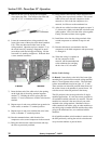
1) On the first machine in the network, open the
Power$ync II
™
control panel by removing the five
screws on the face. Tilt the hinged face down to
expose the circuit boards and power supply inside.
2) Remove one of the hole plugs on the back of the
control enclosure. Insert the end of the
communications cable and bring it to the far right,
lower corner of the enclosure. Make certain that
there are a few inches of extra length at this point.
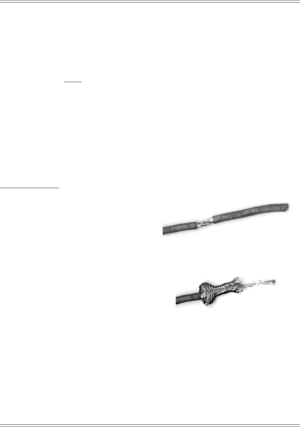
3) Remove 1.5" of the outer insulating cover. Carefully
retract the braided wire shielding to expose the bare
ground wire and the foil cover for the two insulated
wires.
4) Remove excess braided wire shielding, being careful
not to damage the ground wire.