


Section III - Installation
Quincy Compressor
®
- QSD™ 21
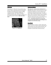
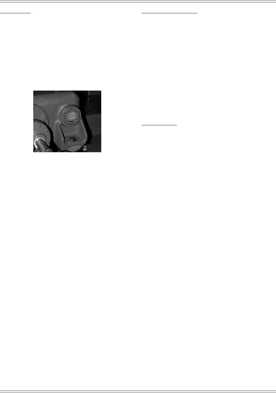
Fluid Level
The compressor is filled at the factory with the correct
amount of fluid. A fluid tag is provided which identifies
the type of fluid installed when the unit was shipped.
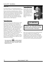
The fluid level is monitored by a sightglass with the
compressor running. The fluid level should be
maintained in the run zone. Fluid can be added by
removing the fill plug after the machine is shut down and
any internal pressure is relieved. DO NOT OVER
FILL.
Fluid Level Sightglass
Compressor Rotation
The compressor rotation must be checked prior to
start-up. Proper rotation is counter-clockwise as viewed
from the power-input end. The power-input end of the
compressor is marked with an arrow (located on the
motor adapter) noting the proper rotation. To check for
proper rotation, briefly jog the start button, allowing the
motor to turn two or three revolutions. Observe the drive
element for correct direction. If incorrect rotation is
observed, lock out power supply, reverse electrical leads
L
1
and L
3
at the motor starter. Recheck for correct
rotation. Allowing the compressor to rotate in the
wrong direction will result in extensive damage to the
compressor and will void warranty.
Fan Rotation
After the compressor rotation is checked, check the fan
rotation. Fan air flow should be outward, pushing the air
out the discharge vent of the acoustical enclosure. The
discharge vent is located just above the service line
connection on the end of the acoustical enclosure.