


Section VI - Servicing
Quincy Compressor
®
- QSD™ 29
Seal Installation
1) Apply a thin coat of compressor fluid to the outer
face of the seal wear sleeve and seal lip.
2) Cover the keyway in the compressor shaft with
masking tape so there is no chance of damage
occurring to the seal face during installation.
3) Apply Loctite
®
515 or 518 to the gearbox seal
adapter mounting flange. Use a roller to apply a
uniform, thin coat on the flange. Remove any excess
Loctite
®
around the fluid feed hole.
4) Install the shims in the same order as removed.
Thickest shims should be facing the seal adapter.
Thinnest shims should be in the middle of the shim
stack.
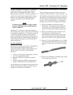
5) Slide the proper seal installation sleeve against the
wear sleeve with the taper toward the end of the
input shaft. Lubricate the seal lips and installation
sleeve with compressor fluid. Carefully slide the
seal adapter with the new seal installed over the end
of the rotor shaft and up against the adapter bore.
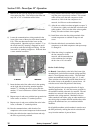
6) Align the fluid feed hole with the slot on the seal
adapter and evenly draw the adapter into the bore,
install the four retaining bolts and tighten to the
specified torque. Remove the installation sleeve.
Airend Sealing System
The airends have a redundant shaft seal arrangement that
consists of three segments:
1) A primary set of seals on the dry side with a
pressurized buffing air flow.
2) A sinuous seal with an air dam.
3) An atmospheric fluid drain on the bearing side.
The sealing system incorporates a redundant seal system
to ensure no fluid enters the compressor chamber. The
seal consists of multiple, floating carbon ring seals and a
sinuous path to prevent bearing fluid from migrating into
the compression chamber. In addition to the physical
seals and a drain pocket, there is a positive flow of
buffing air introduced in the floating carbon rings to
create a pressure differential which sweeps fluid to the
drain pocket. The buffing air for stage one is supplied
from the interstage piping through a pressure regulator.
The pressure regulator is factory set at 4-5 PSI. The
pressure setting should be checked at every service
interval and adjusted if necessary. Outlet of the buffing
air is routed through collection filters. These filters
collect the fluid vapors normally present in the buffing
air drain. The filters should be drained occasionally.
Collection levels and frequency of draining will vary
depending on operating conditions. If a drastic change in
the collection levels occur without a change in operating
conditions, call the factory for service.
There is a smoke eliminator to remove and collect trace
amounts of fluid vapor and return them to the gearcase.
If the collection filter for the smoke eliminator requires
frequent draining, replace the smoke eliminator.
NOTE
Do not restrict the air flow from the vents located
at the outlet end of the package. Doing so may
cause fluid leaks.