


Section VI - Servicing
28 Quincy Compressor
®
- QSD™
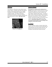
Input Shaft Seal
NOTE
The QSD
™
airend does not contain a scavenge
system. A small fluid weep from the seal is
normal.
Compressor shaft seals are wear items that may
eventually have to be replaced. The input shaft seal on
QSD
™
units is field serviceable. The internal carbon ring
seals on the individual stages are not field serviceable.
To replace the input shaft seal, a complete understanding
of the installation procedure and special tools are
required. Should you decide to replace the seal yourself,
ask your Quincy distributor for the complete illustrated
instructions (available as a Service Alert) at the time you
order the seal and special tools (see parts book for shaft
seal and tool kit part numbers). If your distributor does
not have a copy of these instructions, they can be ordered
from Quincy Compressor at no charge.
Shaft seal replacement on QSD
™
units requires the
removal of the drive motor to allow use of the wear
sleeve removal and installation tools:
1) Remove coupling guards and coupling halves.
2) Remove drive motor.
3) Remove the drive coupling hub and key from the
compressor shaft.
4) Remove the four bolts that secure the seal adapter to
the suction housing.
5) Insert two of the seal adapter retaining bolts into the
seal adapter jack holes and turn clockwise pushing
the seal adapter away from the gearcase housing.
6) Check the inboard face of the seal adapter to make
sure no shims are removed. Do not lose or damage
shims since they need to be reused. Disassemble
the seal adapter for inspection or service by taking
the following steps:
After removing the seal adapter, do not allow the
outer face of the bearing to move. This will cause
the bull gear and shaft to fall in the gearbox,
damaging the gear and bearings.
a) With the face of the seal adapter up, insert two small,
flat screwdrivers under the outer lip of the fluid
slinger and pop the slinger from the seal adapter
bore.
b) Using a brass drift, tap the shaft seal assembly from
the seal bore.
c) Inspect both seal lips for excessive wear, lip flaws or
damage.
d) Inspect the outer o-ring on the fluid slinger for cuts
or nicks.
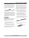
e) To remove the seal wear sleeve, slide the wear sleeve
removal tool over the end of the shaft and allow the
jaws of the tool to snap on the backside of the wear
sleeve. Tighten the outer shell of the tool down over
the inner jaws. Using a ratchet and socket, turn the
puller jackscrew clockwise in against the end of the
compressor shaft. Do NOT use an impact wrench
with this tool.
Preparation for New Seal Installation
1) Inspect the compressor shaft for burrs or deep
scratches at the wear sleeve area. Using a 100 grit
emery cloth, lightly sand horizontally any rust or
Loctite
®
that was between the wear sleeve and shaft.
Using a fine file or emery cloth, deburr the key area
of the rotor shaft. Cover the keyway with masking
tape to prevent any damage to the new seal during
installation.
2) Clean the seal adapter with clean, fast drying solvent.
Place the outer face of the seal adapter on a flat, hard
surface. Remove the new triple-lip seal from the
package and inspect for damage or imperfections on
the seal lips.
3) Position the seal so the two lips that face the same
direction face the gear and the single lip faces the
drive motor.
4) With the lips of the seal facing the correct direction,
apply a thin coat of Loctite
®
290 to the outer steel
case of the seal and position the seal in the seal
adapter bore. Insert the seal driver over the seal.
Insert the proper wear sleeve driver in the seal driver
and tap the new seal into the bore with a medium
sized hammer.
4) Preheat the seal wear sleeve to 350°F
in a small oven.
Do not preheat in warm oil. Apply a thin film of
Loctite
®
to the inner diameter of the wear sleeve and
immediately install on the compressor shaft using the
proper wear sleeve driver. Drive the wear sleeve on
the shaft until the driver bottoms on the shaft
shoulder.
!
CAUTION