


Section VIII - Power$ync II
™
Operation
Quincy Compressor
®
- QSD™ 57
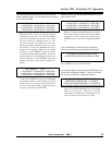
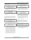
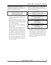
Press the UP arrow key at Network Diagnostic Menu 3 to
display the network diagnostic screen:
A:T5L09 B:T4L09 C:TOL00 D:T4L05
E:TOL00 F:TOL00
NETWORK CONNECTION DATA CONFIDENCE
This display gives an overall view of network
operations. The letter to the left of the colon is the
machine ID. To the right of the colon is the letter
T followed by a number and the letter L followed
by a number. The T number reflects the condition
of the countdown timer. If valid communication
between machines is not maintained, this timer will
begin to count down from 5. As soon as
communications can be confirmed, the counter is
reset. The control is designed to deal with a certain
degree of miscommunication. A well connected
and communicating network will show the numbers
4 or 5 after the T. If the T number is 3 or less,
communication to that particular compressor is
not satisfactory. To the right of the timer number
is the list state number. A number from 00 to 09
indicates the operating state of the compressor.
Any other number should be disregarded. Other
numbers may be displayed when another machine
on the network is being started. The different
operating states indicated by these numbers are:
00 - Trim control for the network has passed to
the left. This will usually indicate a machine that
is in the process of timing out and shutting down,
is already shut down or is not scheduled to be
operating.
01 - Trim control for the network has passed to
the left.
02 - Trim control for the network is currently being
passed to the left.
03 - 07 - Trim control for the network is at this
machine.
08 - Trim control for the network is currently being
passed to the right.
09 - Trim control for the network has passed to
the right.
The example shown indicates that the ‘A’ machine is
running fully loaded and has passed trim control to the
right in the sequence, the ‘B’ machine is running fully
loaded and has also passed trim control to the right in the
sequence and the ‘D’ machine has trim control. The ‘C’
machine is either not in the scheduled sequence or the
power to that machine has been turned off. The T
numbers, 4 and 5, show that the network is
communicating well with the three operating machines.
This display also shows that there is no communication
with any of the other possible network nodes.
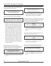
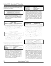
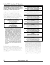
NETWORK DIAGNOSTIC MENU 5
NETWORK LOAD DELAY TIME ______ XX
(SECONDS)
UP FOR NEXT MENU/DOWN FOR PREVIOUS MENU
This menu shows the time, in seconds, that the
compressor will delay in passing the pointer
downward. This is to allow pressure fluctuations
time to level out, if there is a drop in pressure.
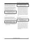
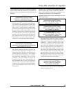
Press ENTER to return to the Compressor Diagnostic
Menu.
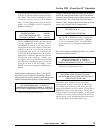
Press F3 to enter the Transducer Parameter Check Menu.
This menu allows diagnostics of possible faults in the
pressure and temperature transducers by providing an
indication of their operating condition.
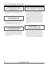
**PACKAGE DISCH PRESSURE TRANSDUCER**
A/D CONVERTER READING______ OFFSET______
COMPUTED PRESSURE READING______
UP FOR NEXT MENU/DOWN FOR PREVIOUS MENU
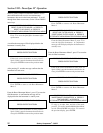
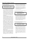
A/D CONVERTER READING shows the voltages
present at the input on the A/D converter on the
board. The pressure transducers provide a voltage
input which are measured at the input connectors
(second pin from top at each connector). These
voltages should match reasonably closely. The
offset shows how far the voltage is OFF from the
ideal value. The computed reading shows the value
that the electronic control will display. It will show
decimal values and negative values, if present. This
is valuable in verifying that a zero pressure reading
is correct.