


Section VIII - Power$ync II
™
Operation
36 Quincy Compressor
®
- QSD™
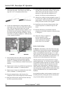
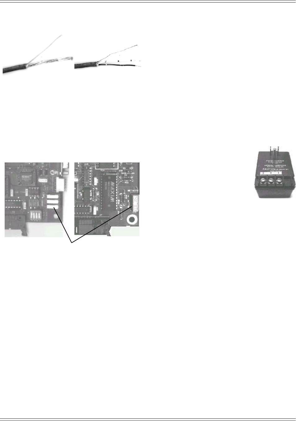
5) Remove the foil cover to expose the two internal
wires and nylon filler. Trim off the nylon filler and
strip 3/8" to 1/2" of insulation off the wires.
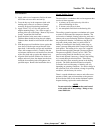
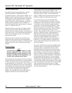
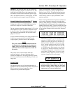
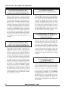
6) Locate the communications wiring terminal in the
lower right corner of the main circuit board (marked
J10). There are three small white levers on the
wiring terminal. Open the top lever, marked “1” on
the circuit board, by inserting a fingernail or small
screwdriver under the left edge and lifting. Lift the
lever until it is standing straight out. 1B boards have
a screw terminal connector.
J10
1A BOARD 1B BOARD
7) Insert the bare end of the white wire in the opening
on the right side of the wiring terminal segment
marked “1”. Holding the wire in place, push the
number “1” lever back down to lock the wire into the
terminal.
8) Repeat steps six and seven with the bare ground wire
in the center, or number “2” terminal position.
9) Repeat steps six and seven with the blue wire in the
lower, or number “3” terminal position.
10) Run the communications cable from the first
compressor to the second compressor in the network.
11) Bring the cable into the control enclosure and strip
the wires as previously outlined.
12) Bring another cable into the control enclosure and
strip the wires as previously outlined. This second
cable will be run to the next compressor in the
network or, if this is the last compressor in a
network, it will be run to the terminator box.
13) After the two cables have been stripped to expose 3/
8" of bare wire, tightly twist the blue wire from each
cable together. Next, twist the white wires together.
Finally, twist the two bare wires together.
14) Install these wires into the wiring terminal of the
second compressor as outlined in steps six and
seven.
15) Run the cable that is not attached to the first
compressor to the third compressor and repeat steps
11 through 14.
16) When the wiring is complete on
the last compressor in the
network, run the unattached end
to the terminator box and plug
the box into a 110 volt outlet.
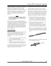
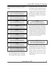
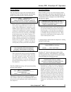
Rocker Switch Settings
1A Boards - Immediately to the left of the lower right
mounting bolt (just below the network wiring terminal)
there is a four-segment rocker switch . The individual
rockers are numbered from left to right, 4, 3, 2, and 1.
These switches are in the ON position when the end of
the rocker closest to the numbers is pressed down. All
switches are set in the ON position at the factory.
The ON position is the correct position for all single
machine applications. It is also the correct position for
all machines installed at the end of a network. The end
machine in a network is the one with only one cable
attached to the wiring terminal. Machines with two
cables attached, both cables going to other machines or
one cable going to another machine and the other cable
going to the terminator box, are considered middle
machines.
On all middle machines switch number 4 must be set to
the OFF position by rocking the switch so that the end
away from the numbers is pressed down.