


Section VIII - Power$ync II
™
Operation
Quincy Compressor
®
- QSD™ 37
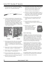
1B Boards - On 1B boards there is no dip switch to set.
Only the termination jumper at J13 needs to be set. This
should be in the ON position on the compressor at the
end furthest from the network terminator power supply.
This is the machine with only 1 cable entering. All other
boards should have this jumper in the OFF position.
Network Voltage Tests on Power$ync II
™
Systems
Voltage tests at J10 on the 140265-1QD board can be
used to do a rough test on network connections.
The top connection should be approximately 2.5-2.9 volts
when operation is normal. The lower connection should
be about 1.9 volts. The voltage generally drops on the
top connection if the terminator, the dip switch or the
jumper are incorrect.
Always check the terminator power supply module to see
if there is power present in its location and that the
voltage output is present as listed on the nameplate.
NOTE
The power outlet for this terminator should be
always powered, not tapped from the compressor
supply. This is to keep the network properly
terminated if one of the compressors is shut off
for service.
The primary cause of network faults other than
terminator settings, is the use of improper cable to
connect the compressors. The wrong cable may work for
short range connections, but will definitely not work over
longer runs.
Network Setup
For applications that see very little demand change or
applications that have demand changes that correspond to
the full capacity of selected compressors, these
compressors may be networked together.
There are nine positions available for machines in a
network (see Compressor Settings and Maintenance
Displays, pages 45-58). The unload and load pressure
settings function much the same way that the pressure
switch settings would in a purely mechanical, multi-
machine controller.
There are nine possible electronic pressure switches that
can be used to determine compressor load and unload
settings. When setting up a sequence, remember that the
first machine ID in the sequence will be assigned to the
number one pressure setting. The next machine ID to the
right will be assigned to the number two pressure setting.
A two machine example of this can be easily illustrated
as follows:
1>115U 110L 2>113U 108L 3>000U 000L
4>000U 000L 5>000U 000L 6>000U 000L
7>000U 000L 8>000U 000L 9>000U 000L
UP/DOWN DEADBAND, F1 EDIT, ENTER RETURN
The number one position pressure has been set to
unload at 115 PSIG and load at 110 PSIG. The
number two position has been set to unload at 113
PSIG and load at 108 PSIG. In the sequence ‘AB’,
the ‘A’ machine would run at the 110 to 115 PSIG
setting and the ‘B’ machine would run at the 108
to 113 PSIG setting. If the sequence were changed
to ‘BA’, the ‘B’ machine would run at the 110 to
115 PSIG setting and the ‘A’ machine would run
at the 108 to 113 PSIG setting. In order to rotate
machines through different pressure settings,
sequence changes must be programmed.
Do not set load pressures higher than the full load
pressure rating of the compressor. Do not set
unload pressures higher than the full load
pressure rating of the compressor when
compressors are set to run load/no load.
!
WARNING