


17
GM 3000AC
!
-
(
)
*
+
,
"
#
$
%
&
.
'
"?
"
#
$
%
&
!
*
(
)
'
"?
OPERATING MANUAL
EDITION 05/2007
PART NO. DOC364831
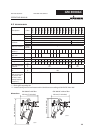
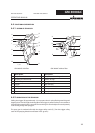
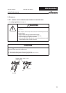
GM 3000AC without fi lterGM 3000AC with fi lter
Description Description
A Suspension hook H Aircap nut and nozzle guard
B Shaping air control knob I Nozzle / air cap
C Tension cap J Spraygun body
D Trigger K Filter housing
E Safety catch L Tube handle
F Air connector M Pivot joint, material
G Material connector N Pivot joint, air
4.4 FUNCTIONAL DESCRIPTION
4.4.1 DESIGN OF SPRAYGUN
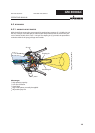
4.4.2 OPERATION OF THE SPRAYGUN
Pulling the trigger (D) approximately 1/2 way opens the air valve allowing atomising and
shaping-air to fl ow through the aircap. When the trigger is pulled further, more resistance
is felt and the material valve is opened. The atomising air control adjusts the total quantity
of air fl owing trough the spray gun.
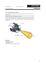
The spray gun is rendered safe with the trigger safety catch (E). (Turn the trigger safety
catch in the spraying direction and fasten in the groove)