


16
CONVENIENCE OUTLETS
ELECTRICAL OPERATION HAZARD
Failure to follow this warning could result in per sonal
injury or death.
Units with conveni ence outlet circuits may use
multiple disconnects. Check convenience outlet for
power status before opening unit for service. Locate
its disconnect switch, if appropriate, and open it.
Tag--out this switch, if necessary.
!
WARNING
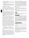
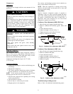
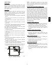
Two types of convenience outlets are offered on 580J
models: Non--powered and unit--powered. Both types
provide a 125-volt GFCI (ground--faul t circui t--interrupter)
duplex receptacle rated at 15-A behind a hinged
waterproof access cover, located on the end panel of the
unit. (See Fig. 16.)
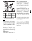
Pwd-CO Transformer
Conv Outlet
GFCI
Pwd-CO
Fuse
Switch
C08128
Fig. 16 -- Convenience Outlet Location
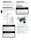
Installing Weatherproof Cover
A weathe rproof while--in--use cover for the
factory--installed convenience outlets is now required by
UL standards. This cover cannot be factory--mounted due
to its depth. It must be installed at unit installation. For
shipment, the conve nience outlet is covered with a blank
cover plate.
The weatherproof cover kit is shipped in the unit’s cont rol
box. The kit includes the hinged cover, a backing plate
and gasket.
IMPORTANT: Disconnect all power to unit a nd
conveni ence outlet.
1. Remove the blank cover pla te at the convenience out-
let; di scard the blank cover.
2. Loosen the two screws at the GFCI duplex outlet, un-
til approximately 1/2--in (13 mm) under screw heads
are exposed.
3. Press the gasket over the screw heads. Slip the back-
ing plate over the screw heads at the keyhole slots
and align with the gasket. Tighten the two screws un-
til snug (do not over--tighten).
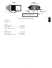
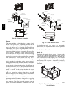
4. Mount the weatherproof cover to the backing plate as
shown in Fig. 17.
COVER - WHILE-IN-USE
WEATHERPROOF
BASE PLATE FOR
GFCI RECEPTACLE
C09244
Fig. 17 -- Weatherproof Cover Installation
5. Remove two slot fillers in the bottom of the cover to
permit service tool cords to e xit the cover. Check for
full closing and latching.
Non--Pow ered Ty pe
This type requires the field installation of a
genera l--purpose 125--volt 15--A circuit powered from a
source elsewhere in the building. Observe national and
local codes when selecting wire size, fuse or breaker
requirements a nd disconnect switch size and location.
Route 125--v power supply conductors into the bottom of
the utility box containing the duplex receptacle.
Unit--Powered Type
A unit--mount ed transformer is factory --installed to
stepdown the main power supply voltage to the unit to
115--v at the duplex receptacle. This option also includes a
manual switch with fuse, located in a utility box and
mounted on a bracket behind the convenience outlet;
access is through the unit’s control box access panel. (See
Fig. 16.)
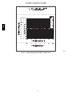
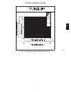
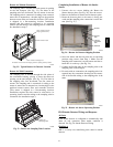
The primary leads to the convenience outlet transformer
are not factory-- connected. Selection of primary power
source is a customer--option. If local codes permit, the
transformer primary leads can be connected at the
line--side te rminals on a unit--mounted non--fused
disconnect or circuit--breake r switch; this will provide
service power to the unit when the unit disconnect switch
or ci rcuit--breaker is open. Other connection methods will
result in the convenience outlet circuit being de--energized
when the unit disconnect or circuit--bre aker is open. (See
Fig. 18.)
580J