


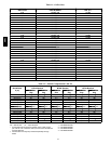
40
SEN
SEN
J20-1
J20-2
C08460
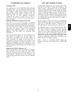
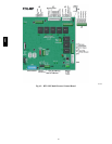
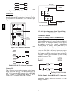
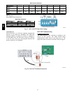
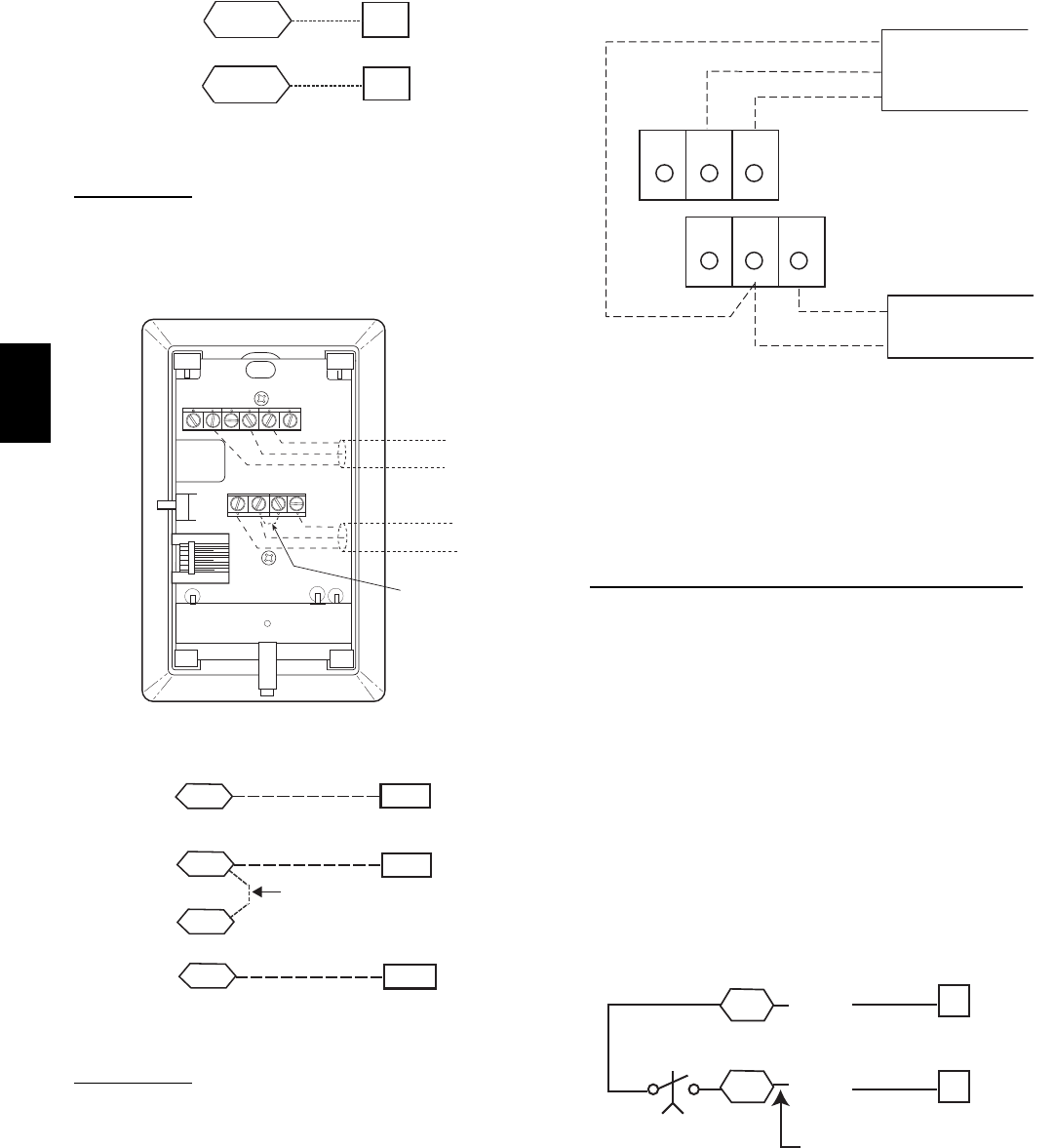
Fig. 46 -- RTU--MP T--55 Sensor Connections
Connect
T-- 56
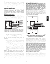
See Fig. 47 for T--56 internal connections. Install a jumper
between SEN and SET terminals as illustrated. Connect
T--56 ter minals to RTU--MP J20--1, J20--2 and J20--3 per
Fig. 48.
2
3
45
61
SW1
SEN
SET
Cool Warm
BRN (GND)
BLU (SPT)
RED(+)
WHT(GND)
BLK(-)
CCN COM
SENSOR WIRING
JUMPER
TERMINALS
AS SHOWN
BLK
(T56)
C08202
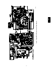
Fig. 47 -- T--56 Internal Connections
SEN J20-1
J20-2
SEN
SET
Jumper
J20-3
SET
C08461
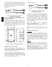
Fig. 48 -- RTU--MP T--56 Sensor Connections
Connect
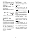
T-- 59
The T--59 space sensor require s a separate, isolated power
supply of 24 VAC. See Fig. 49 for internal connections at
the T--59. Connect the SEN terminal (BLU) to RTU -- MP
J20--1. Connect the COM terminal (BRN) to J20-- 2.
Connect the SET terminal (STO or BLK) to J20-- 3.
OR SET SEN
OPB COM- PWR+
BLU (SPT)
BLK (STO)
24 VAC
SENSOR
WIRING
POWER
WIRING
BRN (COM)
NOTE: Must use a separate isolated transformer.
C07132
Fig. 49 -- Space Temperatur e Sensor Typical Wiring
(33ZCT59SPT)
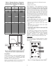
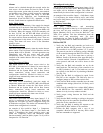
Economizer Controls
Outdoor Air Enthalpy Control (PNO HH57AC077)
The enthalpy control (HH57AC077) is a vailable as a
field--installed accessory to be used with the EconoMi$er2
dampe r system. The outdoor air enthalpy sensor is part of
the enthalpy control. (The separate field--installed
accessory return air e nthalpy sensor (HH57AC078) is
required for differential enthalpy control.)
Loca te the enthalpy control in the economizer hood.
Locate two GRA leads in the factory harness and connect
these leads to enthalpy control sensors 2 and 3. (See Fig.
50.) Connect t he enthalpy control power input terminals to
economizer actuator power leads RED (connect to TR)
and BLK (connect to TR1).
6
7
LCTB
ECON
3
2
Enthalpy
Switch
GRA
GRA
Factory Wiring Harness
C08218
Fig. 50 -- Enthalpy Switch (HH57AC077) Connections
The outdoor e nthalpy changeove r setpoint is set at the
enthalpy controller.
580J