


28
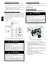
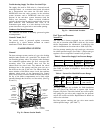
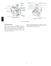
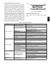
MANIFOLD PRESSURE TAP
GAS
VALVE
BURNERS
C09154
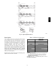
Fig. 36 -- Burner Tray Details
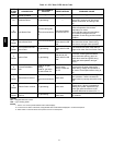
6. Remove igniter wires and sensor wires at the Integ-
rated Gas Unit Controller (IGC). (See Fig. 37.)
7. Remove the 2 screws that attach the burner rack to
the vestibule plate. (See Fig. 34.)
8. Slide the burner tray out of the unit. (See Fig. 36.)
9. To reinstall, reverse the procedure outlined above.
Cleaning and Adj ustment
1. Remove burner rac k from uni t as described in Re-
moval and Replacement of Gas Train section.
2. Inspect burners; if dirty, remove burners from rack.
(Mark each burner to identify its position before re-
moving from the rack.)
3. Use a soft brush to clean burners and cross--over port
as required.
4. Adjust spark gap. (See Fig. 38.)
5. If factory orifice has been removed, check that each
orifice is tight at its threads into the manifold pipe
and that orifice projection does not exceed maximum
valve. (See Fig. 35).
6. Reinstall burners on rack in the same locations as
factory--installed. (The outside crossover flame re-
gions of t he outermost burners are pinched off to pre-
vent excessive gas flow from the side of the burner
assembly. If the pinched crossovers a re installed
betwee n two burners, the flame will not ignite prop-
erly.)
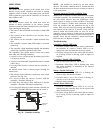
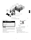
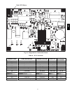
RACEWAY
INTEGRATED GAS UNIT
CONTROLLER (IGC)
HOLE IN END PANEL (HIDDEN)
C08454
Fig. 37 -- Unit Control Box/IGC Location
7. Reinstall burner rack as described in Removal and
Replacement of Gas Train section, above.
Gas Valve — All unit sizes are equipped with 2--stage gas
valves. See Fig. 39 for locations of adjustment screws and
features on the gas valves.
To adjust gas valve pressure se ttings:
IMPORTANT: Leak check all gas connections including
the ma in service connection, gas valve, gas spuds, and
manifold pipe plug. All leaks must be repaired before
firing unit.
Check Unit Operation and Make Necessary
Adjustments
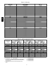
NOTE: Gas supply pressure at gas valve inlet must be
within specified ranges for fuel type and unit size. (See
Table 5, 6, 7, and 8.)
1. Remove manifold pressure tap plug from manifold
and connect pressure gauge or manometer. (See Fig.
36.)
2. Turn on electrical supply.
3. Turn on unit main gas valve.
4. Set room thermostat to call for heat. Verify high--
stage heat operation before attempting to adjust mani-
fold pressure.
5. When main burners ignite, check all fittings, mani-
fold, and orifices for leaks.
6. Adjust high-- stage pressure to specified setting by
turning the plastic adjustment screw clockwise to in-
crea se pressure, counter--clockwise to decrease pres-
sure.
7. Set room thermostat to call for low--stage heat. Adjust
low--stage pressure to specified setting.
8. Replace regulator cover screw(s) when finished.
9. With burner access panel removed, observe unit heat-
ing ope ration in both high stage and low stage opera-
tion. Observe burner flames to see if they are blue in
appearance, and that the flames are approximately the
same for each burner.
10. Turn off unit, remove pressure manometer and re-
place the 1/8 in. pipe fitting on the gas manifold. (See
Fig. 36.)
Limit Switch
Remove blower access panel. Limit switch is located on
the fan deck. (See Fig. 31.)
580J