


34
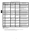
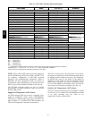
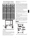
Table 14 – IGC Board LED Alarm Codes
LED
FLASH
CODE
DESCRIPTION
ACTI ON T AKEN BY
CONTROL
RESE T METHOD PROBABLE CAUSE
On Normal Operation — — —
Off Hardwa re Failure No gas heating. —
Loss of power to the IGC. Check 5 amp
fuse on IGC, power to unit, 2 4V circuit
breaker, transformer, and wiring to the
IGC.
2
Flashes
Limit Switch Fault
Gas valve and igniter
Off.
Indoor fan and induce r
On.
Limit switch closed,
or heat call (W) Off.
High temperature limit switch is open.
Check the opera tion of the indoor
(evaporator) fan motor.
Ensure that the supply-air temperature
rise is wi thin the range on the unit
nameplate. Check wiring and limit switch
operat ion.
3
Flashes
Flame Sense Fault
Indoor fan and induce r
On.
Flame sense normal.
P o wer reset for LED
reset.
The IGC sensed a flame when the gas
valve should be closed. Check wiring,
flame sensor, and gas valve operation.
4
Flashes
Four Consecutive Limit
Switch Fault
No gas heating.
Heat call (W) Off.
P o wer reset for LED
reset.
4 consecutive limit switch faults within a
single call for heat. See Limit Switch Fault.
5
Flashes
Ignition Fault No gas heating.
Heat call (W) Off.
P o wer reset for LED
reset.
Unit unsuccess full y attempted ignition for
15 minutes. C heck igniter and flame
sensor elec trode spacing, gaps, etc.
Check flame se nse and igniter wiring.
Check gas valve operat ion and gas
supply.
6
Flashes
Induced Draft Motor
Fault
If heat off: no gas
heating.
If heat on: gas valve
Off and inducer On.
Inducer sense
normal, or heat call
(W) Off.
Inducer s ense On when heat c all Of f, o r
inducer sense Off when heat call On.
Check wiring, voltage, and operation of
IGC motor. Che ck spe ed sensor wiring to
IGC.
7
Flashes
Rollout Swi tch Lo ckout
Gas valve and igniter
Off.
Indoor fan and induce r
On.
Po wer reset.
Rollout switch has opened. C heck gas
valve operation. Check induced-draft
blower whe el is prope rly secured to motor
shaft.
8
Flashes
Interna l Control Lockout No gas heating. Po wer reset.
IGC has sensed internal hardware or
software error. If fault is not cleared by
resetting 24 v power, replace the IGC.
Check gas valve connections to IGC
terminals. BRN lead must be on Pin 11.
9
Flashes
Temporary Software
Lockout
No gas heating.
1 hour auto reset, o r
power reset.
Electrical interference is disrupting the
IGC software.
LEGEND
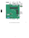
IGC --- Integ rated Gas Unit Control
LED --- Light --- Emitting Diode
NOTES:
1. There is a 3---second pause between alarm code displays.
2. If more than one alarm code exists, all applicable alarm codes will be displayed in numerical sequence.
3. Alarm codes on the IGC will be lost if power to the unit is interrupted.
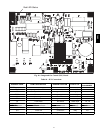
580J