


25
Troubles hooting Supply Fan Motor Overload Trips
The supply fan used in 580J units is a forward--curved
centrifugal wheel. At a constant wheel speed, this wheel
has a characteristic that causes the fan shaft load to
DECREASE when the static pressure in the unit--duct
system increases and to INCREASE when the static
pressure in the unit--duct system decreases (and fan
airflow rate increases). Motor overload conditions
typically develop when the unit is operated with an access
panel removed, with unfinished duct work, in an
econom izer--open mode, or a leak deve lops in the duct
system that allows a bypass back to unit return opening.
Condenser Fan Motor Pr
otection
The conde nser fa n motor is internally protected against
overtemperature.
Control Circuit, 24--V
The control circui t is protec ted against overc urrent
conditions by a circuit breaker mounted on control
transformer TRAN. Reset is manual.
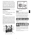
GAS HEATING SYSTEM
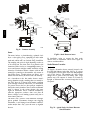
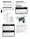
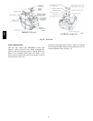
General
The heat exchanger system consists of a gas valve feeding
multiple inshot burners off a manifold. The burners fire
into matching primary tubes. The primary tubes discharge
into combustion plenum where gas flow converges into
secondary tubes. The secondary tubes exit into the
induced draft fan wheel inlet. The induced fan wheel
discharges into a flue passage and flue gases exit out a
flue hood on the side of the unit. The induced draft fan
motor includes a Hall Effect sensor circuit that confirms
adequate wheel speed via the Integrated Gas Control
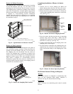
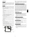
(IGC) board. Safety switches include a Rollout Switch (at
the top of the burner compartment) and a limit switch
(mounted through the fan de ck, over the tubes). (See Fig.
30 and 31.)
INDUCED-
DRAFT
MOTOR
MOUNTING
PLATE
BURNER
SECTION
INDUCED-
DRAFT MOTOR
MANIFOLD
PRESSURE
TAP
ROLLOUT
SWITCH
FLUE
EXHAUST
VESTIBULE
PLATE
BLOWER
HOUSING
GAS
VALVE
C09153
Fig. 30 -- Burner Section Details
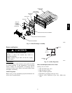
Limit Switch
and Shield
C08284
Fig. 31 -- Limit Switch Location
Fuel Types and Pressures
Natural Gas
The 580J unit is factory--equipped for use with Natural
Gas fuel at elevation under 2000 ft (610 m). See section
Orifice Replacement for information in modifying this
unit for installation at elevations above 2000 ft (610 m ).
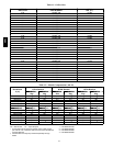
Gas line pressure entering the unit’s main gas valve must
be within specified ranges. (See Table 5.) Adjust unit gas
regulator valve as required or consult local gas utility.
Table 5 – Natural Gas Supply Line Pressure Ranges
UNIT MODEL UNIT SIZE MIN MAX
580J All
4.0 in. wg
(996 Pa)
13.0 in. wg
(3240 Pa)
Manifold pressure is factory--adjusted for NG fuel use.
(See Table 6.) Adjust as required to obtain best flame
characteristic.
Table 6 – Natural Gas Manifold Pressure Ranges
UNIT
MODEL
UNIT
SIZE
HIGH
FIRE
LOW
FIRE
RANGE
580J All
3.5 in. wg
(872 Pa)
1.7 in. wg
(423 Pa)
2.0---5.0 in. wg (Hi)
(498---1245 Pa)
Liquid Propane
Accessory packages are available for field -- installation
that will convert the 580J unit to ope rate with Liquid
Propane (LP) fuels. These kits incl ude new orifice spuds,
new springs for gas valves and a supply line low pressure
switch. See section on Orifice Replacement for details on
orifice size selections.
Fuel line pressure entering unit gas valve must remain
within specified range. (See Table 7.)
580J