


22
SD--TRK4 Remote Alarm Test Procedur e
1. Turn the key switch to the RESET/TEST position for
seven seconds.
2. Verify that the test/reset station’s Alarm LED turns
on.
3. Reset the sensor by turning the key switch to the
RESET/TEST position for two seconds.
4. Verify that the test/reset station’s Alarm LED turns
off.
Remote Test/Reset Station Dirty Sensor T
est
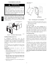
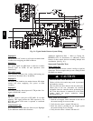
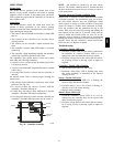
The test/reset station dirty sensor test checks the test/reset
station’s ability to initiate a sensor dirty test and indicate
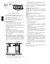
the results. It must be wired to the controller as shown in
Fig. 27 and configured to operate the control ler ’s
supervision relay. For more information, see “Changing
the Dirty Sensor Test.”
1
12
14
1
3
19
15
2
20
3
Reset/Test
Trouble
P
ower
Alarm
S
upe
rv
ision relay
contacts [3]
5
4
1
3
2
SD-TRK4
2
1
TB3
18 Vdc ( )
+
18 Vdc ( )
−
Auxiliary
equipment
+
−
Wire m
ust be
added by installer
Smoke Detector Controller
C08247
Fig. 27 -- Remote Test/Reset Station Connections
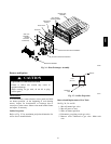
OPERATIONAL TEST HAZARD
Failure to follow this caution may result in personnel
and authority concern.
If the test/reset station’s key switch is left in the
RESET/TEST position for longer than seven seconds,
the detector will automatically go into the alarm state
and activate all automatic alarm responses.
CAUTION
!
OPERATIONAL TEST HAZARD
Failure to follow this caution may result in personnel
and authority concern.
Holding the test magnet to the target area for longer
than seven seconds will put the detec tor into the alarm
state and activate all automatic alarm responses.
CAUTION
!
Dirty Sensor Test Using an SD--TRK4
1. Turn the key switch to the RESET/TEST position for
two seconds.
2. Verify that the test/reset station’s Trouble LED
flashes.
Detector Cleaning
Cleaning the Smoke Detector
Clean the duct smoke sensor when the Dirty LED is
flashing continuously or sooner if conditions warrant.
OPERATIONAL TEST HAZARD
Failure to follow this caution may result in personnel
and authority concern.
If the smoke detector is connected to a fire alarm
system, first notify the proper authorities that the
dete ctor is undergoing mai ntenance then disable the
relevant circuit to avoid generating a false alarm.
CAUTION
!
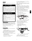
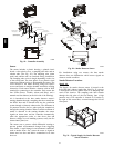
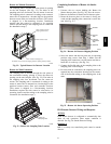
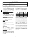
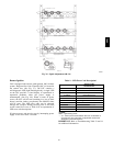
1. Disconnect power from the duct detect or then remove
the sensor’s cover. (See Fig. 28.)
Airow
HVAC duct
Sampling
tube
Retainer
clip
Optic
plate
Optic
housing
Sensor
housing
C07305
Fig. 28 -- Sensor Cleaning Diagram
2. Using a vacuum cleaner, clean compressed air, or a
soft bristle brush, remove loose dirt and debris from
inside the sensor housing and cover.
Use isopropyl alcohol and a lint--fre e cloth to remove
dirt and other contaminants from the gasket on the
sensor’s cover.
3. Squeeze the retainer clips on both sides of the optic
housing then lift the housing away from the printed
circuit board.
4. Gently remove dirt and debris from around the optic
plate and inside the optic housing.
5. Replace the optic housing and sensor cover.
6. Connect power to the duct detector then perform a
sensor alarm test.
580J