


23
INDICATORS
Normal State
The smoke det ector operates in the normal state in the
absence of any trouble conditions and when its sensing
chamber is free of smoke. In the normal state, the Power
LED on both the sensor and the controller are on and all
other LEDs are off.
Alarm
State
The smoke detector enters the alarm state when the
amount of smoke particulate in the sensor’s sensing
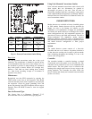
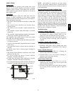
chamber exceeds the alarm threshold value. (See Table 3.)
Upon entering the alarm state:
S The sensor’s Alarm LED and the controller’s Alarm LED
turn on.
S The contacts on the controller ’s two auxiliary relays
switch positions.
S The contacts on the controller’s alarm initiation relay
close.
S The controller’s remote alarm LED output is activated
(turned on).
S The controller’s high impedance multiple fan shutdown
control line is pulled to ground Trouble state.
The SuperDuct duct smoke detector enters the trouble
state under the following conditions:
S A sensor’s cover is removed and 20 minutes pass before
it is prope rly secured.
S A sensor’s environmental compensation limit is reached
(100% dirty).
S A wiring fault between a sensor and the controller is
detected.
An internal sensor fault is detected upon entering the
trouble state:
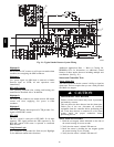
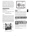
S The contacts on the controller’s supervi sory relay switc h
positions. (See Fig. 29.)
S If a sensor trouble, the sensor ’s Trouble LE D the
controller’s Trouble LED turn on.
S If 100% dirty, the sensor’s Dirty LED turns on and the
controller’s Trouble LED flashes continuously.
S If a wiring fault between a sensor and the controller, the
controller’s Trouble LED turns on but not the sensor’s.
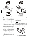
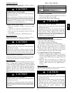
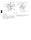
Alarm
Power
Test/reset
switch
Trouble
C07298
Fig. 29 -- Controller Assembly
NOTE: All troubles are latched by the duct smoke
detector. The trouble condition must be cleared and then
the duct smoke detector must be reset in order to restore it
to the normal state.
Resetting Alarm and Trouble Condition T
rips
Manual reset is requi red to restore smoke detector systems
to Normal operation. For installations using two sensors,
the duct smoke detector does not differentiate which
sensor signals an alarm or trouble condition. Check each
sensor for Alarm or Trouble status (indicated by LED).
Clear the condition that has generated the trip at this
sensor. Then reset the sensor by pressing and holding the
reset button (on the side) for 2 seconds. Verify that the
sensor’s Alarm and Trouble LEDs are now off. At the
controller, clear its Alarm or Trouble state by pressing and
holding the manual reset button (on the front cover) for 2
seconds. Verify that the controller’s Alarm and Trouble
LEDs are now off. Replace all panels.
Troubleshooting
Controller’s Trouble LED is On
1. Check the Trouble LED on each sensor connected to
the controller. If a sensor’s Trouble LED is on, de-
termine the cause and make the necessary repairs.
2. Check the wiring between the sensor and the control-
ler. If wiring is loose or missing, repai r or replace as
required.
Controller’s Trouble LED is
Flashing
1. One or both of the sensors is 100% dirty.
2. Determine which Dirty LED is flashing then clean
that sensor assembly as described i n the detector
cleaning section.
Sensor’s Trouble LED is
On
1. Check the sensor’s Dirty LED. If it is flashing, the
sensor is dirty and must be cleaned.
2. Check the sensor’s cover. If it is loose or missing, se-
cure the cover to the sensor housing.
3. Replace sensor assembly.
Sensor’s Power LED is
Off
1. Check the controller’s Power LED. If it is off, de-
termine why the controller does not have power and
make the necessary repairs.
2. Check the wiring between the sensor and the control-
ler. If wiring is loose or missing, repai r or replace as
required.
580J