


39
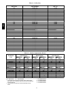
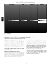
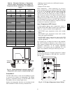
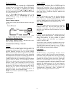
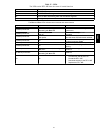
Table 16 – Thermistor Resistance vs Temperature
Values fo r Space Tempera ture Sensor, Supply Air
Temperature Sensor, and Outdoor Air Temperature
Sensor
TEMP
(C)
TEMP
(F)
RESISTANCE
(Ohms)
--- 40 --- 40 335,651
--- 35 --- 31 242,195
--- 30 --- 22 176,683
--- 25 --- 13 130,243
--- 20 --- 4 96,974
--- 15 5 72,895
--- 10 14 55,298
--- 5 23 42,315
0 32 32,651
5 41 25,395
10 50 19,903
15 59 15,714
20 68 12,494
25 77 10,000
30 86 8,056
35 95 6,530
40 104 5,325
45 113 4,367
50 122 3,601
55 131 2,985
60 140 2,487
65 149 2,082
70 158 1,752
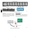
SUPPLY AIR
RETURN AIR
SUPPLY AIR
TEMPERATURE
SENSOR
ROOF
CURB
C08200
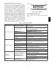
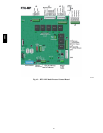
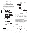
Fig. 44 -- Typical Mo unting Location for Supply Air
Temperature (SAT) Sensor on Small Rooftop Units
EconoMi$er 2
The RTU--MP control is used with EconoMi$er2 (option
or accessory) for outdoor air management. The damper
position is controlled directly by the RTU--MP control;
EconoMi$e r 2 has no internal logic device.
Outdoor air management functions can be enhanced with
field--installation of these accessory control devices:
S Enthalpy control (outdoor air or differential sensors)
S Space CO
2
sensor
S Outdoor air CO
2
sensor
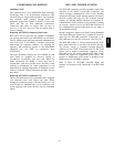
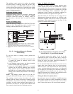
Field Connections -- Field connections for accessory
sensors and input devices are made the RTU--MP, at plugs
J1, J2, J4, J5, J11 and J20. All field control wiring that
connec ts to the RTU--MP must be routed through the
raceway built into the corner post as shown in Fig. 37.
The raceway provides the UL required clearance between
high-- and low--voltage wiring. Pass the control wires
through the hole provided in the corner post, then feed the
wires t horough the raceway to the RTU--MP. Connect to
the wires to the removable Phoenix connectors and then
reconne ct the conne ctors to the board.
Space Temperature (SPT) Senso rs
A field--supplied Bryant space temperature sensor is
required with the RTU-- MP to monitor space temperature.
There are 3 sensors available for this application:
S 33ZCT55SPT, space temperature sensor with override
button
S 33ZCT56SPT, space temperature sensor with override
button and setpoint adjustment
S 33ZCT59SPT, space tempera ture sensor with LCD
(liquid crystal display) scre en, ove rride button, and
setpoint adjustment
Use 20 gauge wire to connect the sensor to the controller.
The wire is suitable for distances of up to 500 ft. Use a
three--conductor shielded cable for the sensor and setpoint
adjustment connections. If the setpoint adjustment
(slidebar) is not required, then an unshielded, 18 or 20
gauge, two--conductor, twisted pair cable may be used.
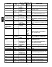
Connect
T-- 55
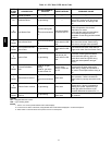
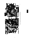
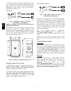
See Fig. 45 for typical T--55 internal connections. Connect
the T--55 SEN terminals to RTU-- MP J20--1 and J20-- 2.
(See Fig. 46.)
2
3
45
61
SW1
SEN
BRN (GND)
BLU (SPT)
RED(+)
WHT(GND)
BLK(-)
CCN COM
SENSOR WIRING
C08201
Fig. 45 -- T--55 Space Tempera ture Sensor Wiring
580J