


24
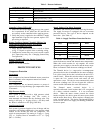
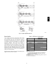
Table 3 – Detector Indicators
CONTROL OR INDICATOR DESCRIPTION
Magnetic test/reset switch
Resets the sensor when it is in the alarm or trouble state. Activates or tests the sen sor when it is in
the normal state.
Alarm LED Indicates the sensor is in the alarm state.
Trouble LED Indicates the sensor is in the trouble state.
Dirty LED
Indicates the amount of environmental compensation used by the sensor
(flashing continuously = 100%)
Power LED Indicates the sensor is energized.
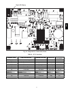
Controller’s Power LED is Off
1. Make sure the circuit supplying power to the control-
ler is operational. If not, make sure JP2 and JP3 are
set correctly on t he c ontroller before applying power.
2. Verify that power is applied to the controller’s supply
input terminals. If power is not present, replace or re-
pair wiring as required.
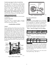
Remo te Test/Reset Statio n’s Trouble LED Does
Not
Flash When Performing a Dirty Test, but
the
Controller’s Trouble LED
Does
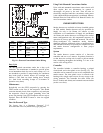
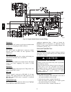
1. Verify that the remote test/station is wired as shown
in Fig. 27. Repair or replace loose or missing wiring.
2. Configure the sensor dirty test to acti vate the control-
ler’s supervision relay. See “Changing Sensor Dirty
Test Operation.”
Sensor’s Trouble LED is On, But the Controller’
s
Trouble LED is
OFF
Remove JP1 on the controller.
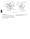
PROTECTIVE DEVICES
Compressor Protection
Overcurrent
Each compressor has internal linebreak motor protection.
Reset is automatic after compressor motor has cooled.
Overtemperatur
e
Each compressor has an internal protector to protect it
against excessively high discharge gas temperatures. Reset
is automatic.
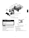
High Pressure
Switch
Each system is provided with a high pressure switch
mounted on the discharge l ine. The switch is
stem--mounted and brazed into the discharge tube. Trip
setting is 630 psig +/-- 10 psig (4344 +/-- 69 kPa) when
hot. Reset is automatic at 505 psig (3482 kPa).
Low Pres sure
Switch
Each system is protected against a loss of charge and low
evaporator coil loading condition by a low pressure switch
located on the suction line near the compressor. The
switch is stem--mounted. Trip setting is 54 psig +/-- 5 psig
(372 +/-- 34 kPa). Reset is automatic at 117 +/ -- 5 psig
(807 +/-- 34 kPa).
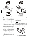
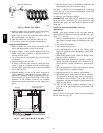
Supply (Indoor) Fan Motor Pr
otection
Disconnect and lockout power when servicing fan motor.
The supply fan motor is equipped wit h an ove rcurrent
protec tion device. The type of device depends on the
motor size. (See Table 4.)
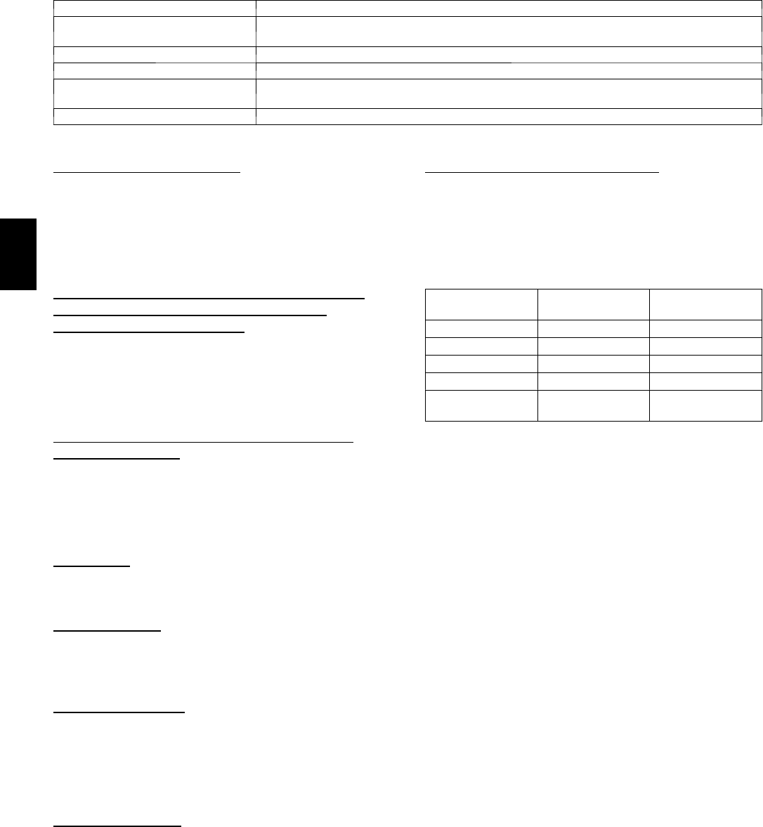
Table 4 – Supply Fa n Motor Protection Devices
Motor Size
(bhp)
Overload Device Reset
1.7 Internal Linebrea k Automatic
2.4 Internal Linebrea k Automatic
2.9 Thermik Automatic
3.7 Thermik Automatic
5.2
External
(Cir cuit Breaker)
Manual
The Internal Linebreak type is an imbedded switch that
senses both m otor current and internal motor temperature.
When this switch reaches its trip setpoint, the switch
opens the power supply to the motor and the motor stops.
Reset is automatic when the motor windings cool down.
The Thermik device is a snap--action overtemperature
protec tion device that is imbedded in the motor windings.
It is a pilot--circuit device that is wired into the unit’s 24-- v
control circuit. When this switch reaches its trip setpoint,
it opens the 24--v control circuit and causes all unit
operation to cease. This device resets automatically when
the motor windings cool. Do not bypass this switch to
correc t t rouble. Determine the cause and correct it.
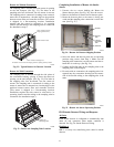
The Exte rnal motor overloa d device is a
specially--calibrated circuit breaker that is UL recognized
as a motor overload controller. It is an overcurrent
device. When the motor current exceeds the circuit
breake r setpoint, the device opens all motor power leads
and the motor shuts down. Reset requires a manual reset
at the overload switch. This device (designated IFCB) is
loca ted on the side of the supply fan housing, behind the
fan access panel.
580J