


31
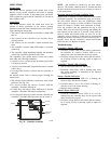
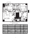
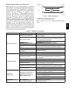
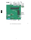
Red LED-Status
C08452
Fig. 40 -- Integrated Gas Control (IGC) Board
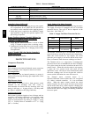
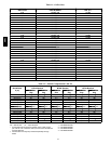
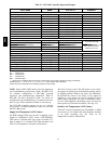
Table 10 – IGC Connections
TERMINAL LABEL POINT DESCRIPTION SENSOR LOCA TION TYPE OF I/O
CONNECTION
PIN NUMBER
INPUTS
RT, C In put power from TRAN 1 control box 24 VAC —
SS Speed sensor gas section analog input J1, 1-3
FS, T1 Flame sensor gas section switch input —
W Heat stage 1 LCTB 24 VAC J2, 2
RS Ro llout switch gas section switch input J2, 5-6
LS Limit switch fan section switch input J2, 7-8
CS Centrifugal switch (not used) — switch input J2, 9 -10
OUTPUTS
L1, CM Induced draft combu stion motor gas section line VAC
IFO Indoor fan cont rol box relay J2, 1
GV Gas valve (heat stage 1) gas section relay J2, 11-12
580J