


27
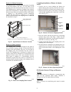
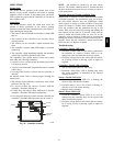
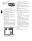
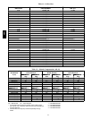
HEATER TUBE
ASSEMBLY
SEAL STRIPS,
SPONGE RUBBER
REGULATOR
GASKET
REGULATOR
RETAINER
WIND CAP
ASSEMBLY
(SHOWN
INVERTED,
AS SHIPPED)
BURNER ASSEMBLY
INDUCER FAN-MOTOR ASSEMBLY
SUPPORT INSULATION ASSEMBLY
C08227
Fig. 34 -- Heat Exchanger Assembly
Burners and Igniters
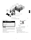
EQUIPMENT DAMAGE HAZARD
Failure to follow this caution may result in
equipment damage.
When working on gas train, do not hit or plug
orifice spuds.
CAUTION
!
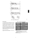
Main Burners
To access burners, remove burner access panel and slide
out burner partition. At the beginning of each heating
season, inspect for deterioration or blockage due to
corrosion or other causes. Observe the main burner flames
and adjust, if necessary.
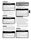
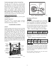
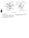
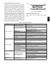
Orifice Projection
Refer to Fig. 35 for maximum projection dimension for
orifice face to manifold tube.
ORIFICE
1.00-in
(25.4 mm)
M
ANIFOLD
PIPE
C08211
Fig. 35 -- Orifice Projection
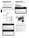
Removal and Replacement of Gas Train
See Fig. 30, 34, and 36.
1. Shut off manual gas valve.
2. Shut off power to unit.
3. Slide out burner partition.
4. Disconnect gas piping at unit gas valve.
5. Remove wires connected to gas valve. Mark each
wire.
580J