


8
9. Finned surfaces should remain wet with cleaning
solution for 10 m inutes.
10. Ensure surfaces are not allowed to dry before rinsing.
Reapply cleaner as needed to ensure 10--minute satur-
ation is achieved.
11. Thoroughly rinse all surfaces with low velocity clean
water using downward rinsing motion of water spray
nozzle. Protect fins from damage from the spray
nozzle.
Evaporator Coil Metering Devices
The metering devices are multiple fixed--bore devices
(Acutrolt) swaged into the horizontal outlet tubes from
the liquid header, located at the entrance to each
evaporator coil circuit path. These are non--adjustable.
Service requires replacing the entire liquid header
assembly.
To check for possible blockage of one or more of these
metering de vices, disconnect the supply fan contactor
(IFC) coil, then start the compressor and observe the
frosting pattern on the face of the evaporator coil. A frost
pattern should develop uniformly across the face of the
coil starting at each horizontal liquid tube. Failure to
devel op frost at an outle t tube can i ndicate a plugged or a
missing orifice.
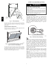
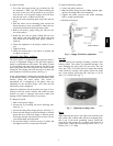
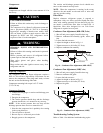
Refrigerant System Pressure Access Por ts
There are two access ports in each compressor--circuit
system -- on the suction tube near the compressor and on
the discharge tube near the compressor. These are brass
fittings with black plastic caps. The hose connection
fittings are standard 1/4 SAE male flare couplings.
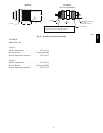
The brass fittings are two--piece High Flow valves, with a
receptacle base brazed to the tubing and an integral
spring-closed check valve core screwed into the base. (See
Fig. 9.) This check valve is permanently assembled into
the core body and cannot be serviced separately. Replace
the entire core body if necessary. Service tools are
available from RCD that allow the replacement of the
chec k va lve core without having to recover the entire
system refrigerant charge. Apply compressor refrigerant
oil to the check valve core’s bottom O-ring. Instal l the
fitting body with 96 +/-- 10 in-lbs (Nm) of torque; do not
overtighten.
PURONR (R--410A) REFRIGERANT
This unit is designed for use with Puron (R--410A)
refrigerant. Do not use any other refrigerant in this
system.
Puron (R--410A) re frigerant is provided in pink (rose)
colored cylinders. These cylinders are avai lable with and
without dip tubes; cylinde rs with dip tubes will have a
labe l indicati ng this feature. For a cylinder with a dip
tube, place the cylinder in the upright position (access
valve at the top) when removing liquid refrigerant for
charging. For a cylinder without a dip tube, invert the
cylinder (access valve on the bottom) when removing
liquid refri gerant.
Because Puron (R--410A) refrigerant is a blend, it is
strongly recomm ended that re frigerant always be removed
from the cylinder as a liquid. Admit liquid refrigerant into
the system in the discharge line . If adding refrigerant into
the suction line, use a commercial metering/expansion
devic e at the gauge manifold; remove liquid from the
cylinder, pass it through the metering device at the gauge
set and then pass it into the suction line as a vapor. Do not
remove Puron (R--410A) refrigerant from the cylinder as a
vapor.
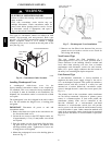
Refrigerant Charge
Amount of refrigerant charge is listed on the unit’s
name plate. Refer to GTAC2--5 Charging, Recovery,
Recycling and Reclamation training manual and the
following procedure s.
Unit panels must be in place when unit is operating during
the charging proce dure. To prepare the unit for charge
adjustment.
No
Charge
Use standard evacuating techniques. After evacuating
system, weigh in the specified amount of refrigerant.
Low--Charge
Cooling
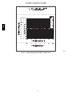
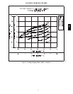
Using Cooling Charging Charts (Fig. 10, 11, 12, and 13),
vary refrige rant until the conditions of the appropriate
chart are met. Note the charging charts are different from
the type normally used. Charts are based on charging the
units to the correct superheat for the various operating
conditions. Accurate pressure gauge and temperature
sensing device are required. Connect the pressure ga uge to
the service port on the suction line. Mount the tempera ture
sensing device on the suction line and insulate it so that
outdoor ambient temperature does not affect the reading.
Indoor--air cfm must be withi n the normal operati ng range
of the unit.
To Use Cooling Charging
Chart s
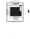
Select the appropriate unit charging chart from Fig. 10,
11, 12, and 13.
S Sizes 08D,F and 12D,F each have one cooling charging
chart
S Size 14D,F has two cooling charging c harts: Circuit A
and Circuit B
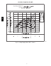
Take the outdoor ambient tempera ture and read the
suction pressure gauge. Refer to chart to determine what
suction temperature should be. If suction temperature is
high, add refrigerant. If suction temperature is low,
carefully recover some of the charge. Recheck the suction
pressure as charge is adjusted.
For 14D,F size, perform thi s procedure once for Circuit A
(using the Circuit A chart) and once for Circuit B (using
the Circuit B chart).
580J