


19
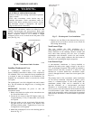
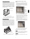
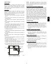
Return Air Without Economizer
The sampling tube is located across the return air opening
on the unit basepan. (See Fig. 22.) The holes in the
sampling tube face downward, into the return air stream.
The sampling tube is connected via tubing to the return air
sensor that is mounted on a bracket high on the partition
between return filter and controller location. (This sensor
is shipped in a flat--mounting location. Installation
requires that t his sensor be relocated to its operating
loca tion and the tubing to the sampling tube be connected.
See installation steps.)
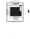
Return Air Detector Sampling Tube
Controller module
Return Air Detector module
(shipping position shown)*
*RA detector must be moved from shipping position to operating position by installer
C07307
Fig. 22 -- Typical Return Air Detector Location
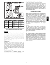
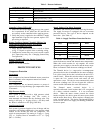
Return Air With
Economize r
The sampling tube is inserted through the side plates of
the economiz er housing, placing it across the return air
opening on the unit basepan. (See Fig. 23.) The holes in
the sampling tube face downward, into the return air
stream. The sampl ing tube is connected via tubing to the
return air sensor that is mounted on a bracket high on the
partition between return filter and controller location.
(This sensor is shipped in a flat--mounting location.
Installation requires that this sensor be relocated to its
operat ing location and the tubing to the sampling tube be
connected. See installation steps.)
Return Air
Sampling Tube
C08129
Fig. 23 -- Return Air Sampling Tube Location
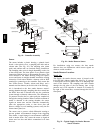
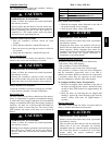
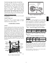
Comple ting Ins tallation of Return Air Smoke
Sensor
1. Unscrew the two screws holding the Return Air
Sensor detector plate. (See Fig. 24.) Save the screws.
2. Remove the Return Air Sensor and its detector plate.
3. Rotate the detector plate so the sensor is facing out-
wards and the sampling tube connection is on the bot-
tom. (See Fig. 25.)
SCREWS
EXHAUST
TUBE
FLEXIBLE
EXTENSION
TUBE
SAMPLING
C08126
Fig. 24 -- Retu rn Air Detecto r Shipping Po sition
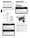
4. Screw the sensor and detector plate into its operating
position using screws from Step 1. Make sure the
sampling tube conne ction is on the bottom and the ex-
haust tube is on the top. (See Fig. 24.)
5. Connect the flexible tube on the sampling inlet to the
sampling tube on the basepan.
6. For units with an economizer, the sampling tube is in-
tegra ted int o the economi zer housing but the connec-
tion of the flexible tubing to the sampling tube is the
same.
C08127
Fig. 25 -- Return Air Sensor Operating Position
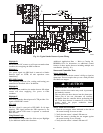
FIOP Smoke Detector Wiring and Response
All Units
FIOP smoke detector is configured to automatically shut
down all unit operations when smoke condition is
dete cted. See Fig. 26, Smoke Detector Wiring.
Highlight
A
JMP 3 is factory--cut, transferring unit control to smoke
dete ctor.
580J