


47
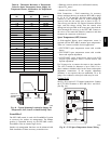
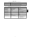
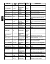
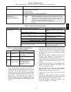
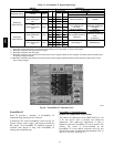
Alarms
Alarms can be checked through the network and/or the
local access. All the alarms are listed in Table 18 with
name , object name, action taken by control, reset method,
and probable cause. There are help screens for each alarm
on the local access display and listed in RTU--MP
Controls, Start--Up, Operation, and Troubleshooting
Instructions (Form 48--50H--T--2T), Appendix A: Help
Screens. Some alarms are explained in detail below.
Safety Chain
Alarm
This alarm occurs immediately if the supply--fan internal
overload trips or if an electric -- heat limit switch trips. The
Unit Status will be Shutdown and the System Mode will
be Disable. When this happens LCTB (R terminal) will
not have 24 VAC, but the RTU -- MP board will still be
powered. All unit operations stop immediately and will
not restart until the alarm automatically clears. There are
no confi gurations for this alarm; it is all based on internal
wiring. This alarm will never occur if Fire Shutdown
Alarm is active.
Fire Shutdo wn
Alarm
This alarm occurs immediately when the smoke detector
senses smoke. The Unit Status will be Shutdown and the
System Mode will be Disable. All unit operations stop
immediately and will not restart until the alarm
automatically clears. If there is not a smoke detector
installed or the smoke detector did not trip, check input
configurations.
Space Temp Sensor Failur
e
This alarm occurs if the space sensor wired to the
RTU--MP is disconnected or shorted for more then 10
seconds. When this occurs the Unit Status will be
Shutdown and the System Mode will be Run. Sensor,
sensor connections, wiring, board connection, and
configurations should be checked for faults or errors.
Alarm will reset automatically when cause is fixed.
SAT S ensor
Alarm
This alarm occurs immediately when t he supply a ir
temperature sensor wired to the RTU--MP is disconnected
or shorted. When this occurs the Unit Status will be
Shutdown and the System Mode will be Run. Sensor,
sensor connections, wiring, board connection, and
configurations should be checked for faults or errors.
Alarm will reset automatically when cause is fixed.
Switch Configuration
Alarm
This occurs if more t han one binary input (inputs 3, 5, 8,
and 9) is configured for the same function. When this
happens the two inputs (or more) configured wrong will
be di sa bled as an inputs. Thi s alarm will autom atically be
cleared when configuration is corrected.
An exa mple of t his would be: Input 3 = Compressor
Safety, input 5 = Fan Status, input 8 = Fan Status, and
input 9 = Humidistat; the alarm would be active, unit
would run, compressor safety and humidistat would
function normally, and Fan Status (inputs 5 & 8) will be
interpreted as “No Function.”
Misconfigured Analog
Input
This occurs if more than one analog input (inputs 1 & 2)
is configured for the same sensor. When this happens the
two inputs will be disabled as inputs. This alarm will
automatically be cleared when configuration is corrected.
An example of this would be: Input 1 = IAQ Sensor, input
2 = IAQ Sensor; the alarm would be active, unit would
run, but the IAQ Sensor (inputs 1 & 2) will be interpreted
as “No Function.”
Third Party
Networking
Third party communication and networking
troubleshooting should be done by or with assistance from
the front end 3rd party te chnician. A Module Status
Report (Modstat) can be run from the BACview
6
,see
Table 19 to perform. This l ists information about the
board status and networking state. For basic
troubleshooting, see Table 20. Refer to the RTU--MP 3rd
Party Integration Guide for additional information.
BACnet MS/TP
1. Verify that the BAS and controller are both set to
speak the BACnet MS/TP protocol. The protocol of
the control ler is set via SW3 (switc hes 3, 4, 5, and 6).
The protocol can also be verified by getting a Modstat
of the controller through the BACview. Hit the “FN”
key and the ’.’ key at the same time to pull up a
Modstat. Scroll to the bottom of the page and there is
a section entitled “Network Communications.” The
active protocol and baud rate will be shown in this
section.
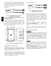
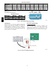
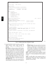
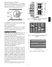
2. Verify that the BAS and controller are set for the
same baud rate. The baud rate of the controller is set
via SW3 (switches 1 and 2). The baud rate can also
be verified via the BACview by obtaining a Modstat.
(See Fig. 59.)
3. Verify that the BAS is configured to speak 2--wire
EIA--485 to the controller. The BAS may have to
configure jum per or DIP switches on their end.
4. Verify that the BAS and the controller have the same
communication settings (8 data bits, No Parity, and 1
stop bit).
5. Verify that the controller has a unique MAC address
on the MS/TP bus. The controller’s MS/TP MAC
address is set by its rotary address switches.
6. Verify proper wiring between the BAS and the
controller.
7. Verify that the BAS is reading or writing to the proper
BACnet objects in the controller. Download the latest
points list for the controller to verify.
8. Verify that the BAS is sending his requests to the
proper MS/TP MAC address of our controlle r.
9. Present the BAS company with a copy of our
controller ’s BACnet PICS so that they know which
BACnet commands are supported.
580J