


41
The enthalpy control receives the outdoor air enthalpy
from the outdoor air enthalpy sensor and provides a dry
conta ct switch input to the RTU--MP controller. A closed
contact indicates that outside air is preferred to the return
air. An open contact indicates t hat the economizer should
remain at minimum position.
Diff erentia l Enthalpy Contr
ol
Differential enthalpy control is provided by sensing and
comparing the outside air and return air enthalpy
conditions. Install the outdoor air ent halpy control as
described above. Add and install a return air enthalpy
sensor.
Return Air Enthalp y
Sensor
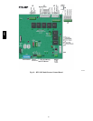
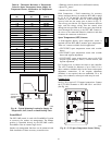
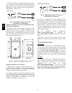
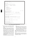
Mount the return --air enthalpy sensor (HH57AC078) in the
return--air duct. The return a ir sensor i s wired to the
entha lpy controller (HH57AC077). (See Fig. 51.)
LED
A
B
C
D
TR TR1
SO
SR
2
3
1
+
+
BRN
RED
GRAY/ORN
GRAY/RED
WIRE HARNESS
IN UNIT
BLK
RED
S
+
(RETURNAIR
ENTHALPY
SENSOR)
S
+
(OUTDOOR
AIR
ENTHALPY
SENSOR)
ENTHALPY CONTROLLER
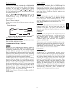
NOTES:
1. Remove factory-installed jumper across SR and + before connecting
wires from return air sensor.
2. Switches shown in high outdoor air enthalpy state. Terminals 2 and 3
close on low outdoor air enthalpy relative to indoor air enthalpy.
3. Remove sensor mounted on back of control and locate in outside air-
stream.
C06019
Fig. 51 -- Outs ide and Return Air Enthalpy
Sensor Wiring
To wire the return air enthalpy sensor, perform the
following:
1. Use a 2--conductor, 18 or 20 AWG, twisted pair cable
to connect the return air enthalpy sensor to the
enthalpy controller.
2. At the enthalpy control remove the factory--installed
resistor from the (SR) and (+) terminals.
3. Connect the field--supplied RED wire to (+) spade
connec tor on the return air enthalpy sensor and the
(SR+) terminal on the enthalpy controller. Conne ct
the BLK wire to (S) spade connector on the return air
entha lpy sensor and the (SR) terminal on the enthalpy
controller.
NOTE: The enthalpy control must be set to the “D”
setting for differential enthalpy control to work properly.
The enthalpy control receives the indoor and return
enthalpy from the outdoor and return air enthalpy sensors
and provides a dry contact switch input to the RTU--MP
controller. A closed contact indicates that outside air is
preferred to the return air. An open contact indicates that
the economizer should remain at minimum position.
Indoor Air Quality (CO
2
Sensor)
The indoor air quality sensor accessory monitors space
carbon dioxide (CO
2
) levels. This information is used to
monitor IAQ levels. Several types of sensors are available,
for wall mounting in the space or in return duct, with and
without LCD display, and in combination with space
temperature sensors. Sensors use infrared te chnology to
mea sure the levels of CO
2
present in the space air.
The CO
2
sensors are all factory set for a range of 0 to
2000 ppm and a linear mA output of 4 to 20. Refer to the
instructions supplied with the CO
2
sensor for electrical
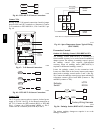
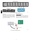
requirements and terminal locations. See Fig. 52 for
typical CO
2
sensor wiring schematic.
C07134
Fig. 52 -- Indoor/Outdoor Air Q uality (CO
2
)Sensor
(33ZCSENCO2) -- Typical Wiring Diagram
To accurately monitor the quality of the air in the
conditioned air space, locate the sensor near a return-- air
grille (if present) so it senses the concentration of CO
2
leaving the space. The sensor should be mounted in a
location to avoid direct breath contact.
Do not mount the IAQ sensor in drafty areas such as near
supply ducts, open windows, fans, or over heat sources.
Allow at least 3 ft (0.9 m) between the sensor and any
corner. Avoid mounting the sensor where it is influenced
by the supply air; the sensor gives i naccurate readings if
the supply air is blown directly onto the sensor or if the
supply air does not have a chanc e to mi x with the room a ir
before it is drawn i nto the return airstream.
Wiring the Indoo r Air Quality Sensor
For each sensor, use two 2--conductor 18 AWG (American
Wire Gauge) twisted--pair cables (unshielded) to connect
the separate isolated 24 vac power source to the sensor
and to connect the sensor to the control board terminals.
580J