


29
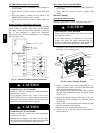
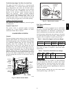
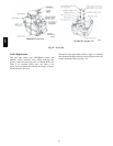
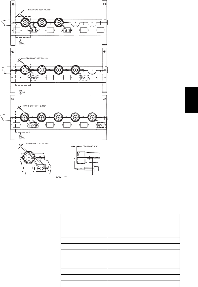
125,000/90,000 BTUH INPUT
180,000/120,000 BTUH INPUT
240,000/180,000 BTUH INPUT
250,000/200,000 BTUH INPUT
C08447
Fig. 38 -- Spark Adjustment (08--14)
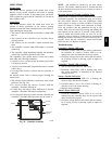
Burner Ignitio n
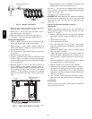
Unit is equipped with a direct spark ignition 100% lockout
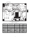
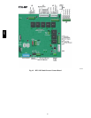
system. Integrated Gas Unit Controller (IGC) is located in
the c ontrol box. (See Fig. 37.) The IGC contains a
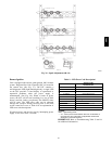
self--diagnostic LED (light--emitting diode). A single LED
on the I GC provides a visual display of operational or
sequential problems when the power supply is
uninterrupted. (See Fig. 40.) When a break i n power
occurs, the IGC will be reset (resulting in a loss of fault
history) and the indoor (evaporator) fan ON/OFF times
will be reset. The L ED error code can be observed
through the viewport. During servicing refer t o the label
on the control box cover or Table 9 for an explanation of
LED error code descriptions.
If loc kout occurs, unit may be reset by interrupting power
supply to unit for at least 5 seconds.
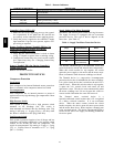
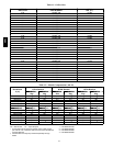
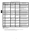
Table 9 – LED Error Cod e Descriptio n*
LED INDICATION
ERROR CODE
DESCRIPTION
ON Normal Operation
OFF Hardware Failure
2Flashes Limit Switch Fault
3Flashes Flame Sense F ault
4Flashes 4 Consecutive Limit Switch Faults
5Flashes Ignition Lockout Fault
6Flashes Induced---Draft M otor Fault
7Flashes Rollout Switch Fault
8Flashes Internal Control Fault
9Flashes Software Lockout
LEGEND
LED --- Light Emitting Diode
* A 3 – second pause exists between LED error code fl ashes. If
more than one error code exists, all applicable codes will be
displayed in numerical sequence.
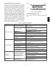
IMPORTANT: Refer to Troubleshooting Table 13 and 14
for additiona l i nformation.
580J