


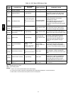

38
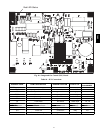
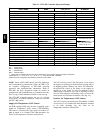
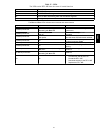
Table 15 – RTU--MP Controller Inputs and Outputs
POINT NAME
BACnet OBJECT
NAME
TYPE OF I/O
CONNECTION PIN
NUMBE R S
INPUTS
Space Tempe rature Se nsor sptsens AI (10K Th ermistor) J20 --- 1, 2
Supply Air Temperature sat AI (10K Thermisto r) J2 --- 1, 2
Local Outside Air Temperature Sensor oatsens AI (10K Thermistor) J2 --- 3, 4
Space Temperature Offset Pot sptopot AI (100K Potentiometer) J20 --- 3
Indoor Air Quality iaq AI (4 --- 20 ma) J4 --- 2, 3
Outd oor Air Quality oaq AI (4 --- 20 ma) J4 --- 5, 6
Safety Chain Feedback safety DI (24 VAC) J1 --- 9
Compressor Safety compsta t DI (24 VAC) J1 --- 2
Fire Shutdown firedown DI (24 VAC) J1 --- 10
Enthalpy Switch enthalpy DI (24 VAC) J2 --- 6, 7
Humidistat Input Status humstat DI (24 VAC) J5 --- 7, 8
CONF IGURABLE INPUTS*
Space Relative Humidity sprh AI (4 --- 20 ma)
J4---2,3 or J4---5,6
Outside Air Relative Humidity oarh AI (4 --- 20 ma)
Supply Fan Status fanstat DI (24 VAC)
J5 --- 1,2 or J5 --- 3,4 or
J5 5,6 or J5---7,8
Filter Status filtstat DI (24 VAC)
Remote Occupancy Input remocc DI (24 VAC)
OUTPUTS
Economizer Comma nded Position econocmd 4 --- 20ma J2 --- 5
SupplyFanRelayState sf DO Relay (24VAC , 1A) J1 --- 4
Compressor 1 Relay State comp_1 DO Relay (24VAC , 1A) J1 --- 8
Compressor 2 Relay State comp_2 DO Relay (24VAC , 1A) J1 --- 7
Heat Stage 1 Relay State heat_1 DO Relay (24VAC , 1A) J1 --- 6
Heat Stage 2 Relay State heat_2 DO Relay (24VAC , 1A) J1 --- 5
Po wer Exhau st Re lay State aux_2 DO Relay (24VAC , 1A) J11 --- 3
Dehumidification Relay State humizer DO Relay (24VAC, 1A) J11 --- 7, 8
LEGEND
AI --- Analog Input
AO --- Analog Output
DI --- Discrete Input
DO --- Discrete Output
* These inputs (if installed) take the place of the default input on the specific channe l according to schematic.
Parallel pins J5 --- 1 = J2 --- 6, J5 --- 3 = J1 --- 10, J5 --- 5 = J1 --- 2 are used for field --- installation.
Refer to the input configuration and accessory sections for more detail.
NOTE: Refer to RTU--MP Controls, Start-Up, Operation,
and Troubleshooting Instructions (Form 48--50H--T--2T)
for complete configuration of RTU --MP, operating
sequence s and troubl eshooting information. Refer to
RTU--MP 3rd Party Integration Guide for details on
configura tion and t roubleshooting of connected networks.
Have a copy of these manuals avail able at uni t start--up.
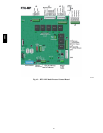
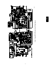
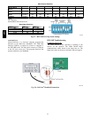
The RTU--MP controller requires the use of a Bryant
space sensor. A standard thermostat cannot be used with
the RTU--MP system.
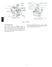
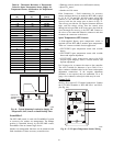
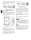
Supply Air Temperature (SAT) Sensor
On FIOP--equipped 580J unit, the unit is supplied with a
supply--air temperature (SAT) sensor (33ZCSENSAT).
This sensor is a tubular probe type, approx 6--inches (12.7
mm) in length. It is a nominal 10 --k ohm thermistor. See
Table 16 for temperature--resistance characteristic.
The SAT is factory--wired. The SAT probe is wire-- tied to
the supply--air opening (on the horizont al opening end) in
its shipping position. Remove the sensor for installation.
Re--position the sensor in the flange of the supply--air
opening or in the supply air duct (as required by local
codes). Drill or punch a 1/2--in. hole in the flange or duct.
Use two field--supplied, self--drilling screws to secure the
sensor probe in a horizontal orientation. (See Fig. 43.)
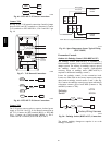
Outdoor Air Temperature (OAT) Sensor
The OAT is factory--mounted in the EconoMi$er 2 (FIOP
or accessory). It is a nominal 10k ohm thermistor attached
to an eyelet mounting ring. See Table 16 for
temperature--resistance characteristic.
580J