


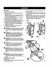
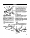

I!_STIIIG CI_II,N[P
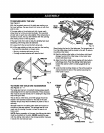
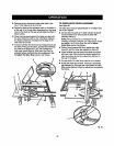
MITERFENCE KNOB ATI'ACHMEN'T
MITER HOLDER BOLT
FENCE
HOLE"A"
\ ,
LOCATORPiN
INDICATOR
TABLESLOT
HOLE=B"
QUICKSTOP HOLE"C" Fig.20
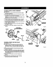
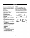
TO LOCK SLIDING MITER TABLE
See Flours21.
The mitertable elides allowingthe operatorto elidethe
workplsce acrossthe saw,A miterslidelock ismounted
on the front of the miter table to lock it inplace.The miter
slidelock is placed ina slot on the baseto align themiter
tabla with theh'ont edge ofthe saw table. The sliding
miter table shouldbe locked for any cutinwhichthe
operatorprefersa fixed table.
• To lock the miter table with the baseprojectingtothe
front, place miterslide lockin the backslot onthe
base.
• To lockthe miter table with the base projectingto the
back, place miter slide lockin thefront slot on the
base.
MITER
SLIDELOCK
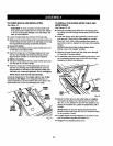
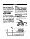
TO CHECK SL|D|NG M_'ER TABLE ASSEMB!3/'
The square relationshipbetween theblade and the miter
fence as it travels the entire distancefrom thefrontto the
rear ofthe miter table baseduringa cutisvery important
for m_ng preciseand accurate cuts.The slidingmiter
table assemblyhasbeen presetat the factory. However,
misallgnment duringshippingor requirementsfor very
preciseand accurate cutsmay requirerce[ignment.
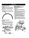
To avoidunnecessarysetups arid ad.iuatments,we
suggestthatyou checkthesesetups carefullywith a fram-
ing square and make practicecuts inscrapwood before
making finishcuts ingood workpisces.
NOTE: Followthegeneralrule ofmeasuring twice and
cuttingonce.
Do not loosen any screws.Once screwshavebeen loos-
ened, settings mustbe reset.
Two basic checks shouldbe made before usingthe miter
table"(1) themiter base must be parallelto the bladeas
the table slides fTomthe front to back, and (2)the miter
fence mustbe squareto the blade when set at exactly
zero (0") on therafter table scats.
NOT_ The miter tablehas adjus_ant screwsfor squar-
ingmiter fence tc bladeand maintaining0° scalesettings
when miterbaseadjustments arersc,uired.These checks
and adjus't_entsare exp_ined in step-by-step procedures
inthe Opera#onsectionend depend on each other.
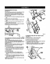
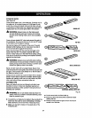
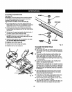
TO INSTALL ACCESSORY TABLE
See Figure22.
• Fit the tabs on theback of theaccessorytable intothe
rear rail.
• Posi_onthe sloton the undersideof the accesaory
table ontothe frontrailand tightenthe lever securely.
NOTE: To usetheoptionalrouteraccessories included
with this product, refertothe Operationsectionfor usage.
ACDESSORY
TABLE
TO
LOCK REARRNL
SLOT8FORLOCKING
MITERTABLE
Fig. 21
\
TO
UNLOCK
LEVER
FITUP OFT_B,LE
IKTOREARRAIL
Fig. 22
21