


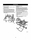
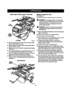

ACCESSORY TABLE USAGE
Th|saccessory table hasbeen spec'dtcaltydesignedfor
usewith listedCraftsmenRoutars.The holepatternon the
accessory table hasnotbeen drffladtoaccommodateall
reuters. Reutersmust notexceed 3 HP (maximumdevel-
oped) or weigh morethan 12-1/2 Ibs.Reutersmust have
took-onswitch feature.
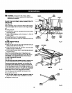
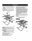
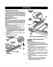
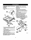
TABLE CLAMP|NG BRACKET
See Figure 51.
The lever on the accessory table wilt.tighten the table se-
curelyto the front rail.The weightofthe muter may cause
the accessory table to loosenorhavemovementst the
rearof the table. Toavoidthis, installthetable clamping
bracket.
NOTE: Positionthe table clampingbracket sothat the
accessorytable iscenteredover it.
II Slide one of theT-nutsintothefrontchannelof the
rearrail and underthe aooeseorytable.
• The table clamping bracketfitsin the bottomslot of
the rear railand the slottedtop ofthe bracketwraps
aroundthe raisedportion on the undersideofthe
accessorytable.
• Secure wlth a 5/16 in.washer and a 5/16-18 x 3/4 in.
knob bolt.
• Tighten the knobbolt securely.
TABLECLAMPINGBRACKET
SHOWNCOMPLETELY _
ASSEMBLED__,._
ACCESSORY L L_L)_
T.,E
TABLECLAMPING
BRACKET
T-NUT
_/'16in.WASHER
KNOBBOLT
END
CAP
Fig. 51
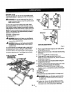
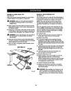
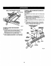
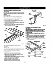
T-NUTBETWEEN
ADJUSTMENT
SCREWS
REAR
ADJUSTMENT
SCREW
RIPFENCESHOWNLOCKEDAGAINSTSAWBLADE
Fig, 52
TO INSTALL T-NU'£_ FOR GUIDE FENCE
BRACKETS
See Figures52.53.
• Placeripfence againstblade and lock in place,
• Usingthe appropriatehex key suppliedwithyourtable
saw,remove the rearadjustmentscrewand washeron
top of the rip fence.
• Slideone ofthe T-nutsintothe top channelof ripfence
and placebetween the two adjustmentscrews.
NOTE: T-nutsinstallfrom the rearof the ripfence.
• Replacethewasher and the rearadjustmentscrewand
tighten securely.
• Checkthe ripfsncs for squarsnesswith ths saw blade,
• Unlocktheripfence, slideitaway from thesaw blade,
and lockit in place,
Slidethe fourremainingT-nutsintothetop channelof
ripfence.
NOTE:FiveT-nutsshouldbe inthe top channelof
the ripfencewith onlyone ofthem between the
adjustmentscrewson therip fence.
37