


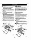
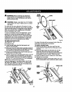
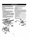

TO SET THE B_VEL INDICATOR AND BEVEL
STOPS AT 0_ AND 45 ° (SQUARING THE BLADE)
Figure62.
The angle sa_mgs oFthe saw havebeen set at the _ac-
tory and, unlessdamaged inshipping,shouldnot require
settingduringassembly. After extensive use, itmay need
to be checked.
• Unplugthe saw.
• Pushthe bevellooking leverto the right.Turnthe
t_eight/beve{ adjustinghandwhsel to angleL'heblade.
Use • combinationsquareto check squareness
between theblade and saw table.
• If the blade is not perfectlyvertical(0_),loosenthe lock
nut on the 0° bolt _nsidethe cabinet, positionthe blade,
adjustthe bolt, then retightenlock nut. See Figure62,
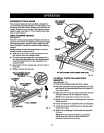
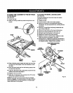
insall, if the banal indicatoris not at zero, adjust_tw_.h
the "twoscrews above the slot, besidethe heighVbevel
adjusting handwheel.
• Turn theheighVbeveladjustingha.ndwhesluntilthe
bottom of the blade has moved completelyto theleft
side ofthe slot. Lock the angleby pushing the bevel
_ockinglever to the left.
BOLT
BEVEL HEIGHT
ADJUSTING
LOCKINGLEVEE[ HANDWHEEL
O"BOLT
BEVEL
INDICATOR
LOCK
NUT
Fig. 62
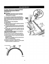
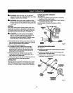
• Ifthe bladeis not anexact 45°, loosenthe lock nut
on the 45° boltinsidethecabinet, positionthe blade,
adjustthe bolt, then retighten lock nut.
• Make a test cut.
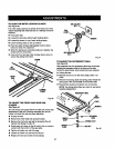
TO ADJUST THE MITER GAUGE
See Figure63.
You can setthe miter gaugeat O° and plusor minus45°
with the mitergaugestop pin andadjustablestop screws.
NOTE The miter gaugeprovidescloseaccuracy inangled
cuts.Forveryclosetolerances,testcutsarerecommended.
• Loosenknoband pull out on stoppin torotate miter
gaugebasepaststop screws.
• Loosenthe lockn_t ofthe 0° stop screwst the stop
pinwith a 8 rnmwrench.
• Place a 90" squareagainstthe m_ar gaugerodand the
miter gauge base.
• Ifthe rod isnotsquare, loosenthe knob, adjustthe rod,
and tightenthe knob.
• Adjustthe 0°atop screw untilitrestsagainstthe stop
pin.
• Adjustthe plusend minus 45° stop screwsusinga 45°
triangle and the stepsabove.
MITER
GAUGEBASE
MITER_
GAUGEROD
LOCK/
NUT
m
O"ADJUSTABLE
STOPSCREW
45"ADJUSTABLE
STOPSCREW
Fig. 63
42