


12
ENGLISH
Installation
1. The machine is heavy. Carefully lift
it out of its shipping carton with the
help of another person.
(The manufacturer recommends
that you keep the shipping carton
and all packing materials in case the
machine needs to be
shipped for
service or repair. If you discard the
packing materials, do so in observ-
ance of and in compliance with all
environmental laws, rules and regu-
lations regarding disposal and recy-
cling that apply at y
our site.)
3
Note:
Do not install rubber feet if the
machine is going to be mounted on the
optional machine stand. The machine
stand is not included in standard deliv-
ery, but can be purchased separately.
For more information, see chapter 11.
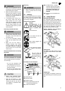
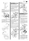
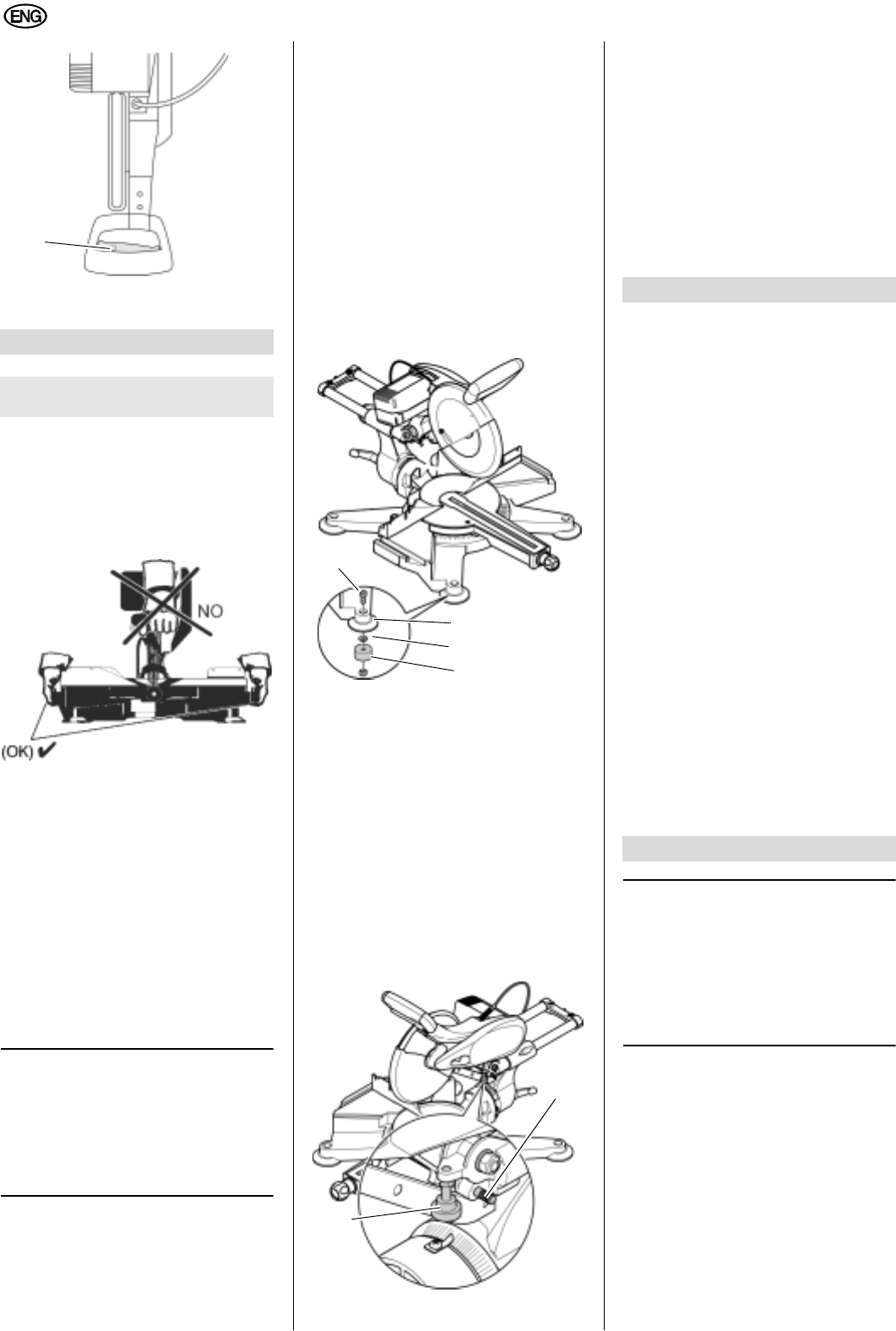
2. Turn the machine over to install the
rubber feet:
The feet must be accessible from
all directions.
Before proceeding, be sure that
the machine is standing firmly in
place even while ti
pped over.
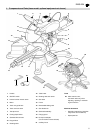
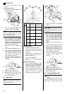
3. Fit the nut (36) into the hole on the
bottom of the rubber foot.
4. Insert the Allen head screw (33) into
the machine’s foot from the top. Fit
the washer (34) on the screw (33)
and attach the rubber foot (35) with
the previously inserted nut (36) to
the screw (33) by hand and start to
tighten.
5. To do so hold the screw (33) with
the 6mm Allen wrench.
6. Hand tighten only!
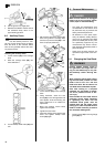
7. Place the machine on a flat and
sturdy surface, large enough to
allow for all necessary movements
and adjustments.
All four feet must firmly rest on
the base.
The ideal height for the base is
32 inches.
The machine must remain stable,
in particular when cutting work
pieces which could cause it to tip.
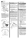
8. Push the sawhead assembly slightly
down and pull the transport locking
pin (37) out.
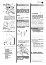
Transport
1. The transport lock
ing pin (37) must
be inserted for transport.
2. Depending on what kinds of cuts
were made previosuly, it may be
necessary to adjust the limit screw
(38) for the adjustment of the cutting
depth. This allows th
e saw head to
be fully lowered, after which the
transport locking pin (37) can then
be inserted.
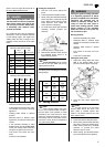
96q cutting angle range for bevel
cuts (48q left through 48q right) with
five preset stops.
110q cuttin
g angle range for miter
cuts (50q left through 60q right) with
ten preset stops.
Soft start.
Cutting depth adjustment for making
grooves with integrated limit screw.
Easy mobility due to lightweight
con-
struction.
Precise and sturdy die-cast alumin-
ium construction.
TCT saw blade.
Easy saw blade change. The saw
blade can be held with the saw
blade lock. No disassembly of the
protective devices required.
Maximum cutting depth
3 3/16".
Maximum cutting width 11 1/4".
Ergonomic and easy for both left-
handed and right-handed operation.
Installation of auxiliary fence possi-
ble.
3
Note:
In this chapter the essential oper-
ating elements of the machine are intro-
duced.
The proper use of the machine is
described in chapter 8, "Operation".
Read this chapter in its entirety before
using the saw for the first time.
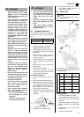
ON/OFF switch
x To turn the motor on, press and hold
the ON/OFF switch (3 9) in the han-
dle. To stop the motor, release the
ON/OFF switch.
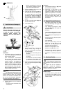
4. Installation and transport
A CAUTION
Do not carry the machine by the
handle; the handle is not designed
to bear the weight of the entire
machine. When carrying the
machine, hold it on both sides of
the base.
32
33
34
35
36
37
38
5. Special Product Features
6. Machine Details