17
ENGLISH
piece is cut at an angle other than 90° to
the fence and material surface.
For compound miter cuts the maximum
dimensions of the work pieces depends
on both cutting angles - the angle of the
rotating table and the tilt angle of the
sawhead. These are s
hown in the table
below.
Starting position:
Sawhead assembly fully raised.
Cutting depth limit screw set to max-
imum depth. Limit screw is securely
tightened.
Rotating table locked in desired
position.
Sawhead tilted to desired angle
against the work piece's surface and
locked.
If the sawhead assembly is tilted
between 22.5° and 48° to the right:
loosen the Phillips head screw and
swing the hinged fence to the rear.
Lock screw of t
he track arm loos-
ened.
Track arm not extended.
Cutting the work piece:
1. Hold the work piece against the
fence.
2. Press and hold the ON/OFF switch .
3. Slowly swing the sawhead assembly
all the way down, holding t
he handle
firmly. When sawing exert only mod-
erate pressure. This keeps the
motor speed from dropping.
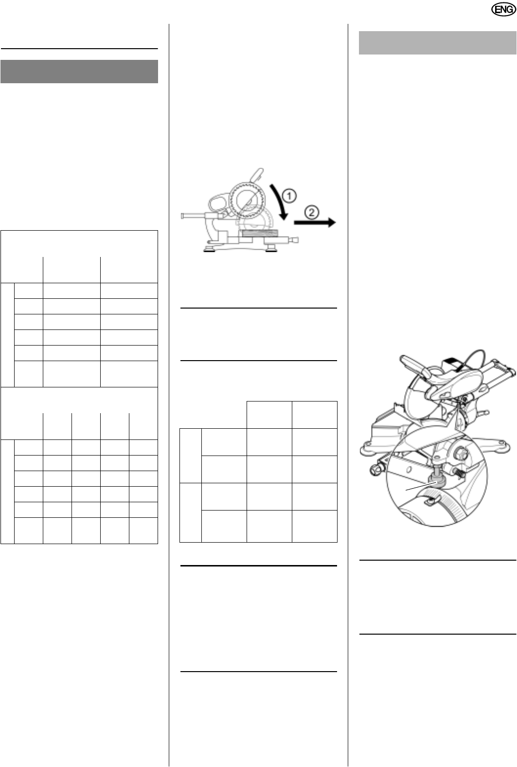
4. For wider work pieces pull sawhead
assembly forward (towards the
operator).
5. Cut work piece in a single pass.
6. Release the ON/OFF switch and let
the sawhead slowly return to its
upper starting position.
3
Note:
Crown moulding can be cut with
the back on the saw ta ble and the top
edge against the fence.
For cutting crown moulding the following
settings apply:
8.5 Making Grooves
3
Note:
During groove cutting only a par-
tial cut, up to a certain depth, is made in
the work piece. This operation is made
possible by use of the track arm, which
allows the sawhead assembly to move
horizontally over
the work piece and the
limit screw, which allows for adjustment
of a given cutting depth.
Starting position:
Sawhead assembly fully raised.
Sawhead tilted to desired angle
against the work piece's surface and
locked.
Rotating table locked in desired
position.
Lock screw of the track arm loos-
ened.
Track arm not extended.
Cutting the work piece:
1. Adjust the cutting depth limit screw
(51) to the desired depth for the
groove and then tighten it securely.
2. Hold the work piece against the
fence.
3
Note:
For the groove to be cut at the
desired depth across the whole work
piece width, a suitable spacer strip
needs to be placed between the work
piece and the fence.
3. Press and hold the ON/OFF switch .
4. Slowly swing the sawhead assembly
fully down, holding the handle firmly.
When sawing exert only moderate
pressure, to prevent the motor
speed
to drop too much.
5. When sawing, pull sawhead assem-
bly forward (towards the operator).
A DANGER
When making compound miter cuts
the saw blade is much more exposed
than during normal cuts and so the
risk of injury increases. Always stay
a sufficiently safe distance away
from the saw blade.
Work piece width (in.) with sawhead
assembly tilted approximately
22.5°
left and right
48 °
left and right
Rotating table position
15° 10 13/16 10 13/16
22.5° 10 1/4 10 1/4
30° 9 5/8 9 5/8
45° 7 7/8 7 7/8
50° 7 1/16 7 1/16
60 °
right
5 1/2 5 1/2
Work piece width (in.) with sawhead
assembly tilted approximately
22.5°
left
22.5°
right
48 °
left
48 °
right
Rotating table position
15° 2 3/4 2 9/16 1 3/4 13/16
22.5° 2 3/4 2 9/16 1 3/4 13/16
30° 2 3/4 2 9/16 1 3/4 13/16
45° 2 3/4 2 9/16 1 3/4 13/16
50° 2 3/4 2 9/16 1 3/4 13/16
60 °
right
2 3/4 2 9/16 1 3/4 13/16
Sawhead
tilt
Miter angle
Inside corner
Left
side
33.9°
left
31.6°
right
Right
side
33.9°
right
31.6°
left
Outside corner
Left
side
33.9°
right
31.6°
left
Right
side
33.9°
left
31.6°
right
A WARNING
During the groove cutting operation
it is especially important no lateral
pressure is applied to the saw blade.
Otherwise the sawhead may be
kicked up abruptly! Always use a
clamp to hold the work piece in
place when making grooves. Avoid
lateral pressure on the sawhead.
Make sure that the work piece lies
flat and does not jam.
51


